Dell OptiPlex Gs Service Manual (.pdf) - Page 97
Microprocessor and Heat Sink Assembly
 |
View all Dell OptiPlex Gs manuals
Add to My Manuals
Save this manual to your list of manuals |
Page 97 highlights
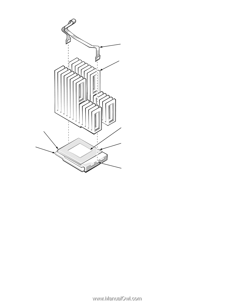
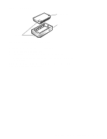
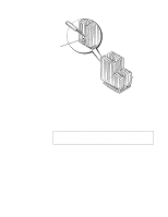
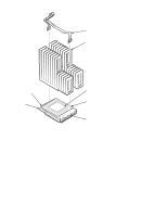
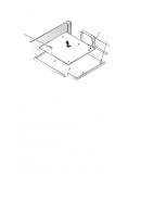
microprocessor securing clip heat sink microprocessor-socket release lever pin-1 corner of socket thermal interface pad (attached to underside of heat sink) microprocessor front of computer right tab Figure 5-21. Microprocessor and Heat Sink Assembly If the replacement heat sink and microprocessor are separate, peel the thermalpad protective cover off the bottom of the heat sink before attaching the heat sink to the microprocessor. To install the replacement microprocessor/heat sink assembly, ensure that the microprocessor-socket release lever is in its fully vertical position to allow the microprocessor pins to easily slip into the socket. When the microprocessor/ heat sink assembly is in place, rotate the microprocessor-socket release lever to its horizontal position. Hook the microprocessor securing clip over the socket tab nearest the right side of the system board, and then snap it over the tab on the opposite side of the socket. NOTE: Pin 1 on the microprocessor is located on the corner with the largest bevel. The pin-1 hole in the microprocessor socket is located on the corner where the holes are in a diagonal pattern. Removing and Replacing Parts in the Midsize System 5-21
-
 1
1 -
2
-
3
-
4
-
5
-
6
-
7
-
8
-
9
-
10
-
11
-
12
-
13
-
14
-
15
-
16
-
17
-
18
-
19
-
20
-
21
-
22
-
23
-
24
-
25
-
26
-
27
-
28
-
29
-
30
-
31
-
32
-
33
-
34
-
35
-
36
-
37
-
38
-
39
-
40
-
41
-
42
-
43
-
44
-
45
-
46
-
47
-
48
-
49
-
50
-
51
-
52
-
53
-
54
-
55
-
56
-
57
-
58
-
59
-
60
-
61
-
62
-
63
-
64
-
65
-
66
-
67
-
68
-
69
-
70
-
71
-
72
-
73
-
74
-
75
-
76
-
77
-
78
-
79
-
80
-
81
-
82
-
83
-
84
-
85
-
86
-
87
-
88
-
89
-
90
-
91
-
 92
92 -
 93
93 -
 94
94 -
 95
95 -
 96
96 -
 97
97 -
 98
98 -
 99
99 -
 100
100 -
 101
101 -
 102
102 -
103
-
104
-
105
-
106
-
107
-
108
-
109
-
110
-
111
 |
 |