Dell OptiPlex Gs Service Manual (.pdf) - Page 59
Front-Panel Inserts, Front-Panel Insert Removal
 |
View all Dell OptiPlex Gs manuals
Add to My Manuals
Save this manual to your list of manuals |
Page 59 highlights
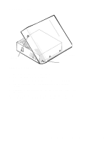
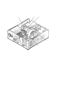
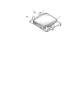
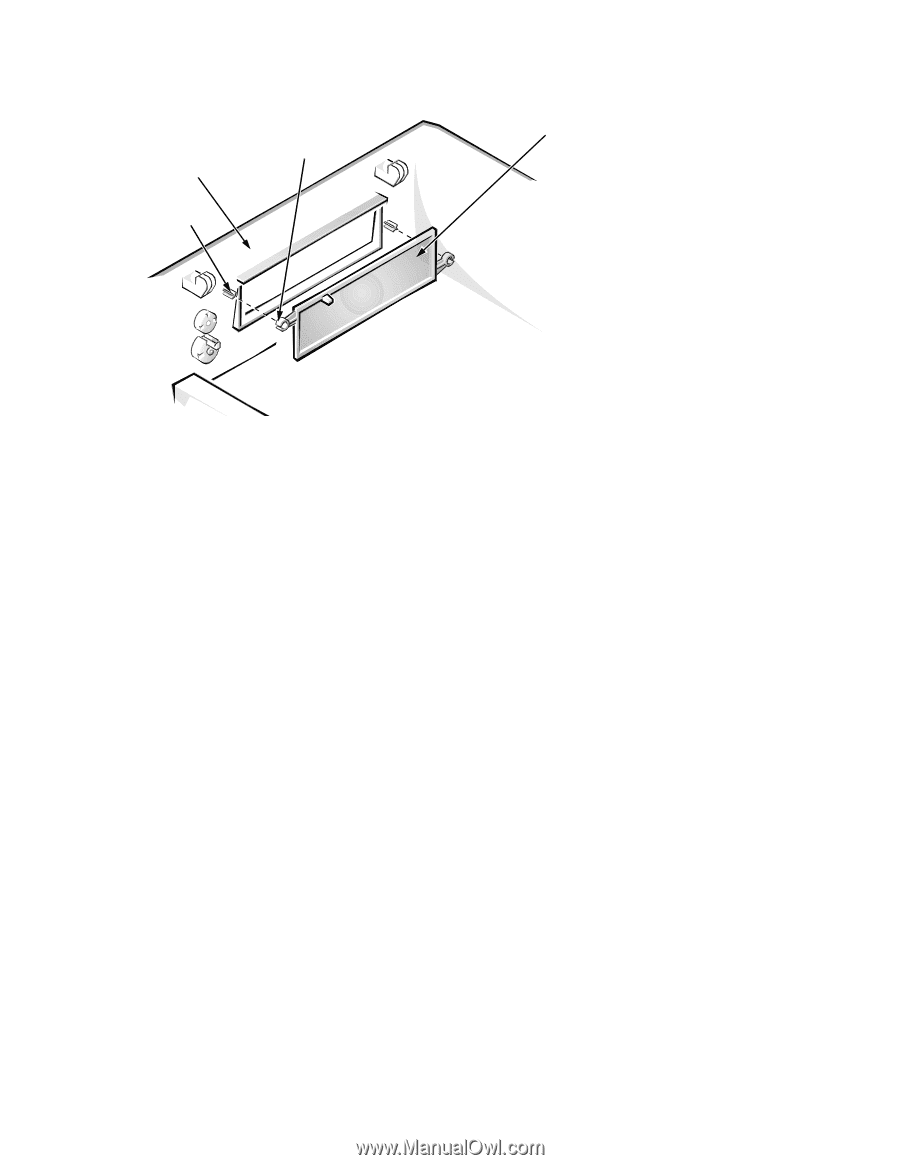
Front-Panel Inserts computer cover (upside down) posts (2) ring-tabs (2) 5.25-inch frontpanel insert Figure 4-3. Front-Panel Insert Removal To remove a front-panel insert, follow these steps: 1. Lay the computer cover upside down on a flat work surface, with the front of the cover facing you. 2. From the front of the cover, use your thumbs to push inward on the insert until it slides off the two posts. To replace a front-panel insert, position the front-panel insert, and then press the ring-tabs over the posts. If necessary, use a 1/4-inch nutdriver to secure the ringtabs. Removing and Replacing Parts in the Low-Profile System 4-5
-
 1
1 -
2
-
3
-
4
-
5
-
6
-
7
-
8
-
9
-
10
-
11
-
12
-
13
-
14
-
15
-
16
-
17
-
18
-
19
-
20
-
21
-
22
-
23
-
24
-
25
-
26
-
27
-
28
-
29
-
30
-
31
-
32
-
33
-
34
-
35
-
36
-
37
-
38
-
39
-
40
-
41
-
42
-
43
-
44
-
45
-
46
-
47
-
48
-
49
-
50
-
51
-
52
-
53
-
 54
54 -
 55
55 -
 56
56 -
 57
57 -
 58
58 -
 59
59 -
 60
60 -
 61
61 -
 62
62 -
 63
63 -
 64
64 -
65
-
66
-
67
-
68
-
69
-
70
-
71
-
72
-
73
-
74
-
75
-
76
-
77
-
78
-
79
-
80
-
81
-
82
-
83
-
84
-
85
-
86
-
87
-
88
-
89
-
90
-
91
-
92
-
93
-
94
-
95
-
96
-
97
-
98
-
99
-
100
-
101
-
102
-
103
-
104
-
105
-
106
-
107
-
108
-
109
-
110
-
111
 |
 |
Removing and Replacing Parts in the Low-Profile System
4-5
F
ront-Panel Inserts
Figure 4-3.
Front-Panel Insert Removal
To remove a front-panel insert, follow these steps:
1.
Lay the computer cover upside down on a flat work surface, with the
front of the cover facing you.
2.
From the front of the cover, use your thumbs to push inward on the
insert until it slides off the two posts.
To replace a front-panel insert, position the front-panel insert, and then press the
ring-tabs over the posts. If necessary, use a
1/4
-inch nutdriver to secure the ring-
tabs.
ring-tabs (2)
posts (2)
computer cover
(upside down)
5.25-inch front-
panel insert