Dell OptiPlex Gs Service Manual (.pdf) - Page 86
Inch Drive Assembly Removal
 |
View all Dell OptiPlex Gs manuals
Add to My Manuals
Save this manual to your list of manuals |
Page 86 highlights
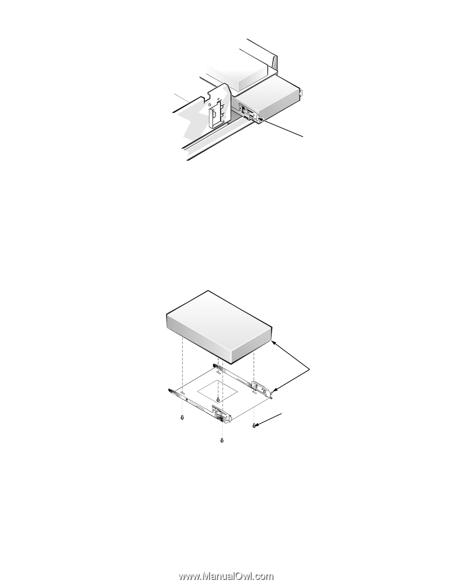
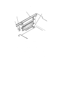
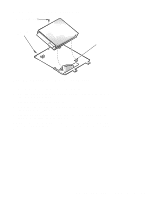
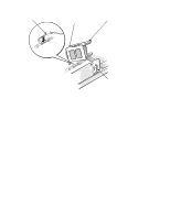
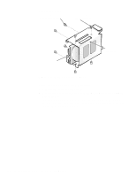
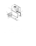
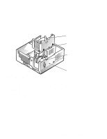
retaining tabs (2) Figure 5-8. 5.25-Inch Drive Assembly Removal To remove a 5.25-inch drive assembly from the middle or lower drive bay, follow these steps: 1. Disconnect the DC power cable and the interface cable from the back of the drive. 2. Press in the two retaining tabs (one on each side of the drive), and slide the drive assembly forward to remove it. 3. Remove the four screws securing the 5.25-inch drive to the drive bracket, and lift the drive out of the bracket (see Figure 5-9). align front of drive flush with tab at front of bracket screws (4) Figure 5-9. 5.25-Inch Drive Removal When you replace the 5.25-inch drive, align the front of the drive flush with the tabs at the front of the drive bracket. Insert the four screws and tighten them in the order stamped on the bottom of the bracket. 5-10 Dell OptiPlex Gs and Gs+ Systems Service Manual
-
 1
1 -
2
-
3
-
4
-
5
-
6
-
7
-
8
-
9
-
10
-
11
-
12
-
13
-
14
-
15
-
16
-
17
-
18
-
19
-
20
-
21
-
22
-
23
-
24
-
25
-
26
-
27
-
28
-
29
-
30
-
31
-
32
-
33
-
34
-
35
-
36
-
37
-
38
-
39
-
40
-
41
-
42
-
43
-
44
-
45
-
46
-
47
-
48
-
49
-
50
-
51
-
52
-
53
-
54
-
55
-
56
-
57
-
58
-
59
-
60
-
61
-
62
-
63
-
64
-
65
-
66
-
67
-
68
-
69
-
70
-
71
-
72
-
73
-
74
-
75
-
76
-
77
-
78
-
79
-
80
-
 81
81 -
 82
82 -
 83
83 -
 84
84 -
 85
85 -
 86
86 -
 87
87 -
 88
88 -
 89
89 -
 90
90 -
 91
91 -
92
-
93
-
94
-
95
-
96
-
97
-
98
-
99
-
100
-
101
-
102
-
103
-
104
-
105
-
106
-
107
-
108
-
109
-
110
-
111
 |
 |