Dell OptiPlex Gs Service Manual (.pdf) - Page 84
Drives, puter. Refer to this when you perform any of the procedures in
 |
View all Dell OptiPlex Gs manuals
Add to My Manuals
Save this manual to your list of manuals |
Page 84 highlights
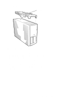
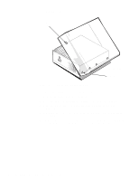
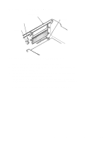
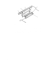
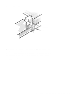
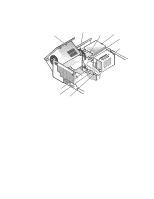
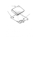
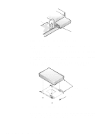
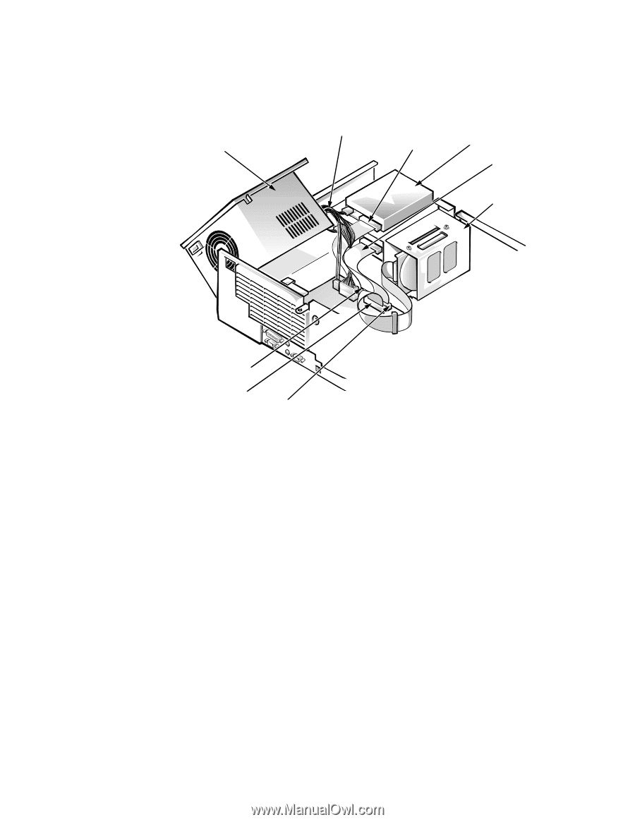
Drives Figure 5-6 shows an example of drive hardware that can be installed in the computer. Refer to this figure when you perform any of the procedures in the following subsections. system power supply (rotated) DC power cable diskette/tape drive interface cable 3.5-inch diskette drive EIDE CD-ROM/tape drive cable hard-disk drive bracket DSKT connector primary EIDE connector (IDE1) secondary EIDE connector (IDE2) Figure 5-6. Drive Hardware 5-8 Dell OptiPlex Gs and Gs+ Systems Service Manual
-
 1
1 -
2
-
3
-
4
-
5
-
6
-
7
-
8
-
9
-
10
-
11
-
12
-
13
-
14
-
15
-
16
-
17
-
18
-
19
-
20
-
21
-
22
-
23
-
24
-
25
-
26
-
27
-
28
-
29
-
30
-
31
-
32
-
33
-
34
-
35
-
36
-
37
-
38
-
39
-
40
-
41
-
42
-
43
-
44
-
45
-
46
-
47
-
48
-
49
-
50
-
51
-
52
-
53
-
54
-
55
-
56
-
57
-
58
-
59
-
60
-
61
-
62
-
63
-
64
-
65
-
66
-
67
-
68
-
69
-
70
-
71
-
72
-
73
-
74
-
75
-
76
-
77
-
78
-
 79
79 -
 80
80 -
 81
81 -
 82
82 -
 83
83 -
 84
84 -
 85
85 -
 86
86 -
 87
87 -
 88
88 -
 89
89 -
90
-
91
-
92
-
93
-
94
-
95
-
96
-
97
-
98
-
99
-
100
-
101
-
102
-
103
-
104
-
105
-
106
-
107
-
108
-
109
-
110
-
111
 |
 |
5-8
Dell OptiPlex Gs and Gs+ Systems Service Manual
D
rives
Figure 5-6 shows an example of drive hardware that can be installed in the com-
puter. Refer to this figure when you perform any of the procedures in the
following subsections.
Figure 5-6.
Drive Hardware
diskette/tape drive
interface cable
DC power cable
DSKT connector
system
power supply
(rotated)
hard-disk
drive bracket
primary EIDE
connector (IDE1)
secondary EIDE
connector (IDE2)
EIDE CD-ROM/tape
drive cable
3.5-inch diskette drive