Dell PowerEdge 1655MC Information and Firmware Update - Page 11
Updating the Network Switch Module Firmware, Setting Up the Remote System Serial Connection Baud Rate
 |
View all Dell PowerEdge 1655MC manuals
Add to My Manuals
Save this manual to your list of manuals |
Page 11 highlights
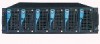
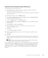
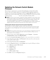
Updating the Network Switch Module Firmware Three firmware components are associated with updating the network switch module firmware. You need to update only the new components. Before updating components, compare the versions from the Dell Support website at support.dell.com with the versions loaded on the network switch module. You can verify the component version on your switch module by typing show version from the command line interface (CLI). NOTE: All three of the firmware components (loader, diagnostics, and runtime) of the network switch module can be updated by connecting the RJ-11-to-serial cable that came with your system to the RJ-11 connector on the switch module. However, only the runtime component can be updated using either the RJ-11 connector or the 10/100/1000 BASE-T uplink ports. It is recommended that the runtime component be updated using the uplink ports connected to the remote system (TFTP server). Setting Up the Remote System Serial Connection Baud Rate This procedure is used for initially setting the serial connection baud rate for the remote system. However, step 2 through step 8 are referenced in each of the component update procedures. NOTE: These procedures assume that you are using Hilgraeve's HyperTerminal Private Edition 6.1 or later. If you are using other terminal emulation software, see the documentation for that software. 1 On your remote system, click the Start button, point to Programs→ Accessories→ Communications, and then click HyperTerminal. 2 From the Connection Description dialog box, enter a name for the new connection. 3 On the HyperTerminal toolbar, click Disconnect to disconnect the serial connection to the network switch module. 4 On the HyperTerminal toolbar, click Properties. 5 From the Properties dialog box, click Configure and set up the COM port as follows: a Set Bits per second to 9600 (default). b Set Data bits to 8. c Set Parity to None. d Set Stop bits to 1. e Set Flow control to None. 6 Click OK to return to the Properties dialog box. Information and Firmware Update 1-7
-
 1
1 -
2
-
3
-
4
-
5
-
 6
6 -
 7
7 -
 8
8 -
 9
9 -
 10
10 -
 11
11 -
 12
12 -
 13
13 -
 14
14 -
 15
15 -
 16
16 -
17
-
18
-
19
-
20
-
21
-
22
-
23
-
24
-
25
-
26
-
27
-
28
-
29
-
30
-
31
-
32
-
33
-
34
-
35
-
36
-
37
-
38
-
39
-
40
-
41
-
42
-
43
-
44
-
45
-
46
-
47
-
48
-
49
-
50
-
51
-
52
-
53
-
54
-
55
-
56
-
57
-
58
-
59
-
60
-
61
-
62
-
63
-
64
-
65
-
66
-
67
-
68
-
69
-
70
-
71
-
72
-
73
-
74
-
75
-
76
-
77
-
78
-
79
-
80
-
81
-
82
-
83
-
84
-
85
-
86
-
87
-
88
-
89
-
90
-
91
-
92
-
93
-
94
-
95
-
96
-
97
-
98
-
99
-
100
-
101
-
102
-
103
-
104
-
105
-
106
-
107
-
108
-
109
-
110
-
111
-
112
-
113
-
114
-
115
-
116
-
117
-
118
-
119
-
120
-
121
-
122
-
123
-
124
-
125
-
126
-
127
-
128
-
129
-
130
-
131
-
132
-
133
-
134
-
135
-
136
-
137
-
138
-
139
-
140
-
141
-
142
-
143
-
144
-
145
-
146
-
147
-
148
-
149
-
150
-
151
-
152
-
153
-
154
-
155
-
156
-
157
-
158
-
159
-
160
-
161
-
162
-
163
-
164
-
165
-
166
-
167
-
168
-
169
-
170
 |
 |