Dell PowerEdge 1655MC Information and Firmware Update - Page 14
Updating the Runtime Component
 |
View all Dell PowerEdge 1655MC manuals
Add to My Manuals
Save this manual to your list of manuals |
Page 14 highlights
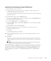
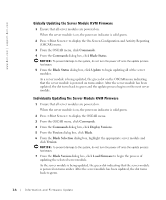
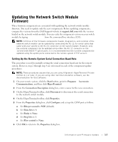
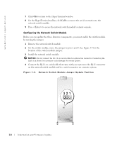
www.dell.com | support.dell.com 3 Type 0 (zero) for image update. 4 Change the remote system's baud rate to 115200 (see "Setting Up the Remote System Serial Connection Baud Rate"). 5 Click Send to access the Send File dialog box. 6 Select Xmodem protocol. 7 Browse and select the file loaderxxx.bix, where xxx is the version of the loader component. 8 Click Send to download the file. The download takes approximately 10 seconds. 9 After the download is complete, press (lowercase L) to update the loader component. 10 After the update is complete, change the remote system's baud rate to 9600 (see "Setting Up the Remote System Serial Connection Baud Rate"). 11 To update other components, press any key to continue, and proceed to "Updating the Diagnostics Component" or "Updating the Runtime Component." If you are not updating any other components, remove the network switch module and move the jumper back to pins 1 and 2 (default). NOTE: If you do not move the jumper back to pins 1 and 2, you will not be able to use ERA/MC console redirection to log into the network switch module. Updating the Runtime Component NOTE: The runtime component can be updated using either the RJ-11-to-serial cable or the 10/100/1000 BASE-T uplink ports. It is recommended that the runtime component is updated using the uplink ports connected to the remote system (TFTP server). See your network switch module documentation for more information about updating the switch module firmware. Perform the following steps to update the switch module's firmware using the R-J11-to-serial cable. 1 With the RJ-11-to-serial cable connected to the network switch module, reset the switch module by unplugging the switch module and then reinserting it. 2 During POST, press to enter the diagnostic mode. If you wait too long and your operating system begins to load let the system complete the load operation, and then repeat step 1 and step 2. 1-10 Information and Firmware Update
-
 1
1 -
2
-
3
-
4
-
5
-
6
-
7
-
8
-
 9
9 -
 10
10 -
 11
11 -
 12
12 -
 13
13 -
 14
14 -
 15
15 -
 16
16 -
 17
17 -
 18
18 -
 19
19 -
20
-
21
-
22
-
23
-
24
-
25
-
26
-
27
-
28
-
29
-
30
-
31
-
32
-
33
-
34
-
35
-
36
-
37
-
38
-
39
-
40
-
41
-
42
-
43
-
44
-
45
-
46
-
47
-
48
-
49
-
50
-
51
-
52
-
53
-
54
-
55
-
56
-
57
-
58
-
59
-
60
-
61
-
62
-
63
-
64
-
65
-
66
-
67
-
68
-
69
-
70
-
71
-
72
-
73
-
74
-
75
-
76
-
77
-
78
-
79
-
80
-
81
-
82
-
83
-
84
-
85
-
86
-
87
-
88
-
89
-
90
-
91
-
92
-
93
-
94
-
95
-
96
-
97
-
98
-
99
-
100
-
101
-
102
-
103
-
104
-
105
-
106
-
107
-
108
-
109
-
110
-
111
-
112
-
113
-
114
-
115
-
116
-
117
-
118
-
119
-
120
-
121
-
122
-
123
-
124
-
125
-
126
-
127
-
128
-
129
-
130
-
131
-
132
-
133
-
134
-
135
-
136
-
137
-
138
-
139
-
140
-
141
-
142
-
143
-
144
-
145
-
146
-
147
-
148
-
149
-
150
-
151
-
152
-
153
-
154
-
155
-
156
-
157
-
158
-
159
-
160
-
161
-
162
-
163
-
164
-
165
-
166
-
167
-
168
-
169
-
170
 |
 |