Dell PowerEdge M620 Owners Manual - Page 30
Installing The Cooling Shroud, System Memory
 |
View all Dell PowerEdge M620 manuals
Add to My Manuals
Save this manual to your list of manuals |
Page 30 highlights
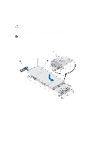
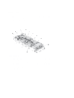
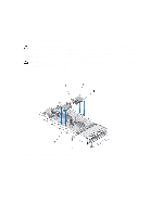
Installing The Cooling Shroud CAUTION: Many repairs may only be done by a certified service technician. You should only perform troubleshooting and simple repairs as authorized in your product documentation, or as directed by the online or telephone service and support team. Damage due to servicing that is not authorized by Dell is not covered by your warranty. Read and follow the safety instructions that came with the product. 1. Position the tabs below the shroud to align with the holes on the heat sink installed on processor socket CPU1. 2. Lower the cooling shroud into the system until the tabs on the sides of the shroud engage with the slots on the blade chassis and the pins under the shroud engage with the holes on the heat sink. 3. Close the blade. 4. Install the blade in the enclosure. System Memory Your system supports DDR3 unbuffered ECC DIMMs (UDIMM ECC) and registered DIMMs (RDIMMs). It supports DDR3 and DDR3L voltage specifications. NOTE: MT/s indicates DIMM speed in MegaTransfers per second. Memory bus operating frequency can be 1600 MT/s, 1333 MT/s, 1066 MT/s, or 800 MT/s depending on: • DIMM type (UDIMM, RDIMM, or LRDIMM) • DIMM configuration (number of ranks) • maximum frequency of the DIMMs • number of DIMMs populated per channel • DIMM operating voltage • system profile selected (for example, Performance Optimized, Custom, or Dense Configuration Optimized) • maximum supported DIMM frequency of the processors The system contains 24 memory sockets split into two sets of 12 sockets, one set per processor. Each 12-socket set is organized into four channels. In each channel, the release levers of the first socket are marked white, the second socket black, and the third socket green. NOTE: DIMMs in sockets A1 to A12 are assigned to processor 1 and DIMMs in sockets B1 to B12 are assigned to processor 2. The following table shows the memory populations and operating frequencies for the supported configurations. DIMM Type DIMMs Populated/ Channel Operating Frequency (in MT/s) 1.5 V 1.35 V UDIMM ECC 1 1333, 1066, and 800 1333, 1066, and 800 2 1333, 1066, and 800 1333, 1066, and 800 RDIMM 1 1600, 1333, 1066, and 800 1333, 1066, and 800 1333, 1066, and 800 1066 and 800 2 1600, 1333, 1066, and 800 1333, 1066, and 800 1066 and 800 1066 and 800 Maximum DIMM Rank/ Channel Dual rank Dual rank Dual rank Quad rank Dual rank Quad rank 30
-
 1
1 -
2
-
3
-
4
-
5
-
6
-
7
-
8
-
9
-
10
-
11
-
12
-
13
-
14
-
15
-
16
-
17
-
18
-
19
-
20
-
21
-
22
-
23
-
24
-
 25
25 -
 26
26 -
 27
27 -
 28
28 -
 29
29 -
 30
30 -
 31
31 -
 32
32 -
 33
33 -
 34
34 -
 35
35 -
36
-
37
-
38
-
39
-
40
-
41
-
42
-
43
-
44
-
45
-
46
-
47
-
48
-
49
-
50
-
51
-
52
-
53
-
54
-
55
-
56
-
57
-
58
-
59
-
60
-
61
-
62
-
63
-
64
-
65
-
66
-
67
-
68
-
69
-
70
-
71
-
72
-
73
-
74
-
75
-
76
-
77
-
78
-
79
-
80
-
81
-
82
-
83
-
84
-
85
-
86
-
87
-
88
-
89
-
90
-
91
-
92
-
93
-
94
-
95
-
96
-
97
-
98
-
99
-
100
-
101
-
102
-
103
-
104
-
105
-
106
-
107
-
108
-
109
-
110
-
111
-
112
-
113
-
114
-
115
-
116
-
117
-
118
-
119
-
120
-
121
-
122
-
123
-
124
-
125
-
126
-
127
-
128
-
129
-
130
-
131
-
132
-
133
-
134
-
135
-
136
-
137
-
138
-
139
-
140
-
141
-
142
-
143
 |
 |
