Dell PowerEdge M620 Owners Manual - Page 54
Installing The System Board, Internal USB key
 |
View all Dell PowerEdge M620 manuals
Add to My Manuals
Save this manual to your list of manuals |
Page 54 highlights
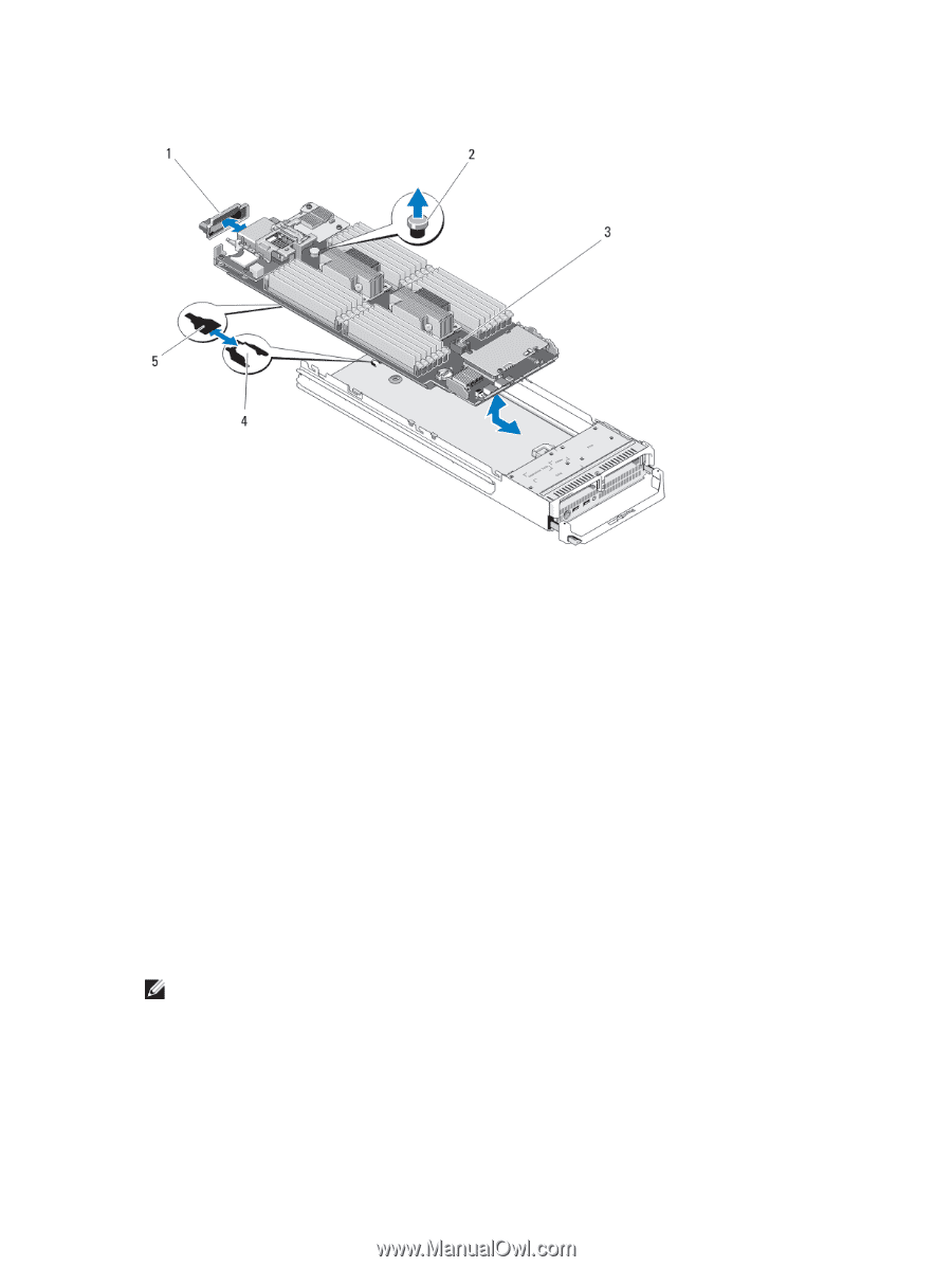
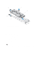
12. Remove the storage controller card/PCIe extender card. Figure 20. Removing and Installing the System Board 1. I/O connector cover 2. retention latch 3. system board 4. tabs on system chassis 5. slots in system board tray Installing The System Board 1. Transfer the following components to the new system board: - Internal USB key - storage controller card/PCIe extender card - SD vFlash card - Memory modules and memory module blanks - Processor(s) and heat sink(s), or processor filler blank - network daughter card 2. Slide the new system board into the open end of the blade chassis until the retention latch or retention pin engages. NOTE: Ensure that the system board plate is parallel with the chassis. When the board assembly is installed correctly, the tabs on the system board pan fit into the corresponding openings in the floor of the blade chassis. 3. Replace the mezzanine card(s) in their original locations. 4. Reinstall the hard-drive/SSD backplane. 54
-
 1
1 -
2
-
3
-
4
-
5
-
6
-
7
-
8
-
9
-
10
-
11
-
12
-
13
-
14
-
15
-
16
-
17
-
18
-
19
-
20
-
21
-
22
-
23
-
24
-
25
-
26
-
27
-
28
-
29
-
30
-
31
-
32
-
33
-
34
-
35
-
36
-
37
-
38
-
39
-
40
-
41
-
42
-
43
-
44
-
45
-
46
-
47
-
48
-
 49
49 -
 50
50 -
 51
51 -
 52
52 -
 53
53 -
 54
54 -
 55
55 -
 56
56 -
 57
57 -
 58
58 -
 59
59 -
60
-
61
-
62
-
63
-
64
-
65
-
66
-
67
-
68
-
69
-
70
-
71
-
72
-
73
-
74
-
75
-
76
-
77
-
78
-
79
-
80
-
81
-
82
-
83
-
84
-
85
-
86
-
87
-
88
-
89
-
90
-
91
-
92
-
93
-
94
-
95
-
96
-
97
-
98
-
99
-
100
-
101
-
102
-
103
-
104
-
105
-
106
-
107
-
108
-
109
-
110
-
111
-
112
-
113
-
114
-
115
-
116
-
117
-
118
-
119
-
120
-
121
-
122
-
123
-
124
-
125
-
126
-
127
-
128
-
129
-
130
-
131
-
132
-
133
-
134
-
135
-
136
-
137
-
138
-
139
-
140
-
141
-
142
-
143
 |
 |