Dell PowerEdge MX7000 EMC OpenManage Enterprise-Modular Edition Version 1.10.2 - Page 70
MX Scalable Fabric architecture, Recommended physical topology
 |
View all Dell PowerEdge MX7000 manuals
Add to My Manuals
Save this manual to your list of manuals |
Page 70 highlights
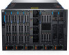
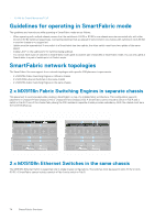
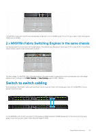
9 MX Scalable Fabric architecture The scalable fabric architecture ties multiple MX7000 chassis into a single network domain to behave like a single logical chassis from a networking perspective. The MX scalable fabric architecture provides multi-chassis Ethernet with: • Multiple 25Gb Ethernet connections to each server sled • No east-west oversubscription • Low "any-any" latency • Scale up to 10 MX7000 chassis • Flexible uplink speeds • Support for non-PowerEdge MX devices such as rack servers For more information, see the PowerEdge MX I/O Guide available at www.dellemc.com. Architectural Overview A scalable fabric consists of two main components - a pair of MX9116n Fabric Switching Engines (FSE) and additional pairs of MX7116n Fabric Expander Modules (FEM) used to connect remote chassis to the FSEs. This is a hardware enabled architecture and it applies irrespective of whether the switch is running in Full Switch or Fabric modes. A total of ten MX7000 chassis are supported in a scalable fabric. Fabric Switching Engine The FSE contains the switching ASIC and network operating system. Traffic that is received from a FEM is mapped to the correct switch interface automatically. Each NIC port has a dedicated 25GbE lane from the NIC through the FEM and into the FSE so there is no port to port oversubscription. Fabric Expander Module An FEM takes Ethernet frames from a compute node and sends them to the FSE and from the FSE to the compute node. There is no switching ASIC or operating system running on the FEM, which allows for a very low latency. This also means that there is no firmware that needs to be updated. The FEM is invisible to the FSE and does not need to be managed in any way. When using dual-port NICs, only the first port on the FEM must be connected to the FSE. The second port is not used. When connecting a FEM to an FSE, the rules to remember are: • FEM in Slot A1 connects to FSE in Slot A1 • FEM in Slot A2 connects to FSE in Slot A2 • FEM in Slot B1 connects to FSE in Slot B1 • FEM in Slot B2 connects to FSE in Slot B2 Topics: • Recommended physical topology • Restrictions and guidelines • Recommended connection order Recommended physical topology The recommended minimum design for a scalable fabric is two chassis with fabric A populated with redundant IOMs. Ideally, the two chassis are located in separate racks on separate power circuits to provide the highest redundancy. Additional chassis only have FEMs and the appear as the image below. 70 MX Scalable Fabric architecture
-
 1
1 -
2
-
3
-
4
-
5
-
6
-
7
-
8
-
9
-
10
-
11
-
12
-
13
-
14
-
15
-
16
-
17
-
18
-
19
-
20
-
21
-
22
-
23
-
24
-
25
-
26
-
27
-
28
-
29
-
30
-
31
-
32
-
33
-
34
-
35
-
36
-
37
-
38
-
39
-
40
-
41
-
42
-
43
-
44
-
45
-
46
-
47
-
48
-
49
-
50
-
51
-
52
-
53
-
54
-
55
-
56
-
57
-
58
-
59
-
60
-
61
-
62
-
63
-
64
-
 65
65 -
 66
66 -
 67
67 -
 68
68 -
 69
69 -
 70
70 -
 71
71 -
 72
72 -
 73
73 -
 74
74 -
 75
75 -
76
-
77
-
78
-
79
-
80
-
81
-
82
-
83
-
84
-
85
-
86
-
87
-
88
-
89
-
90
-
91
-
92
-
93
-
94
-
95
-
96
-
97
-
98
-
99
-
100
-
101
-
102
-
103
-
104
-
105
-
106
-
107
 |
 |
