Dewalt DXGNR5700 Instruction Manual - Page 11
Operation, Know the Generator
 |
View all Dewalt DXGNR5700 manuals
Add to My Manuals
Save this manual to your list of manuals |
Page 11 highlights
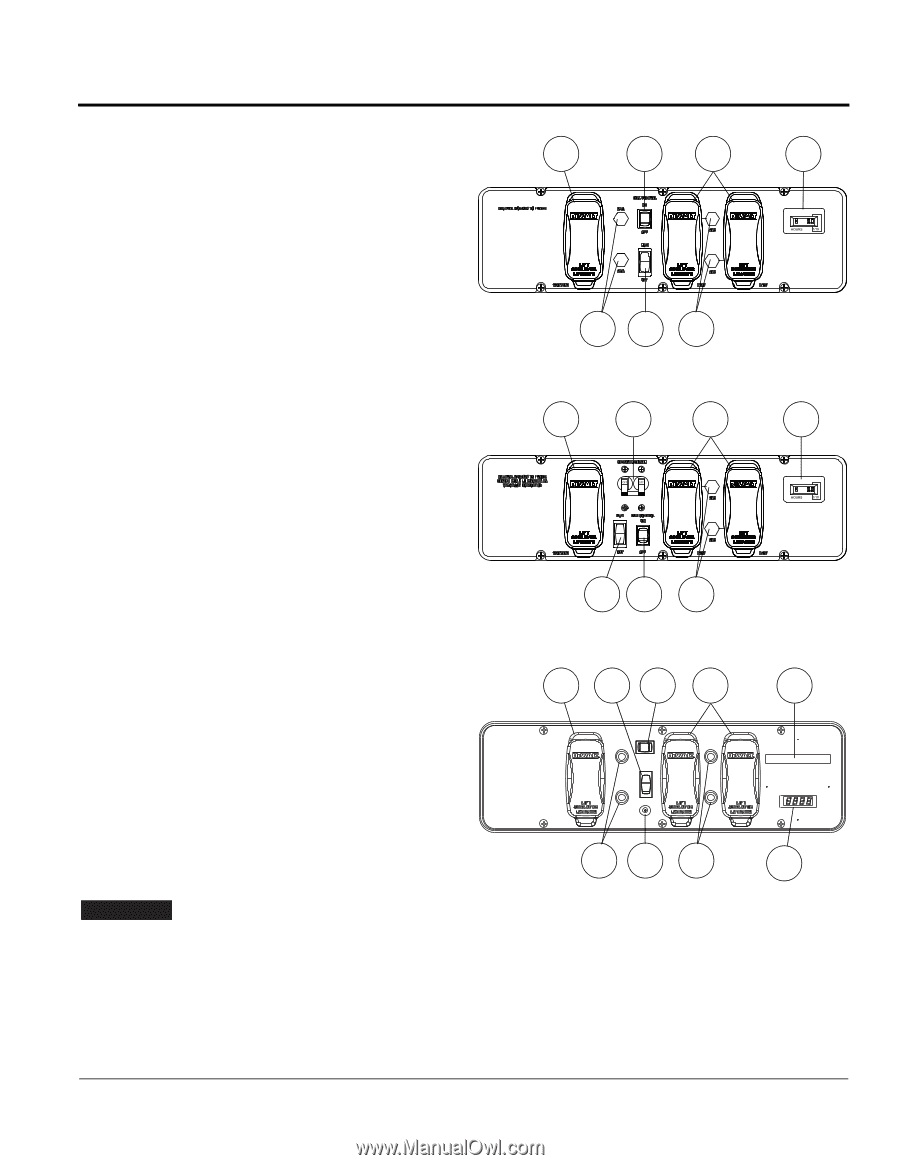
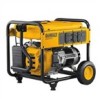
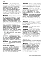
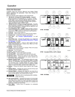
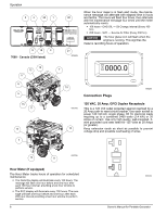
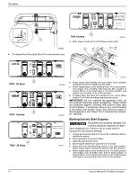
Operation Know the Generator Carefully read the Owner's Manual and Safety Rules before operating the generator. Save this manual for future reference. Become familiar with locations of all components. 1. 120 Volt AC, 20 Amp GFCI Duplex Outlets - Supplies electrical power for the operation of 120 Volt AC, 20 Amp, single-phase, 60 Hz, electrical lighting, appliance, tool and motor loads. It also provides protection with an integral Ground Fault Circuit Interrupter, complete with a press to TEST and RESET button (NEMA 5-20R). 2. 120/240 Volt AC, 30 Amp Locking Receptacle - Supplies electrical power for operation of 120 and/or 240 Volt AC, 30 Amp, single-phase, 60 Hz, electrical lighting, appliance, tool and motor loads (NEMA L14-30R). 3. Circuit Breakers (AC) - CARB models provide a push-toreset circuit breaker to protect the generator against electrical overload. CSA models provide 2-pole circuit breakers. 4. Oil Drain - Use to drain engine oil. 5. Air Filter - Filters intake air as it is drawn into the engine. 6. Choke Lever - Used when starting a cold engine. 7. Fuel Tank - See Product Specifications for tank capacity. 8. Grounding Lug - Ground the generator to an approved earth ground here. See Grounding Generator If Used as Portable for details. 9. Start/Run/Stop Switch - Used to start engine from the starter motor (electric start models only). Must be in Run position to start manually. 10. Muffler - Quiets the engine. 11. Handle - Pivot and retract for storage. Press the springloaded button to move handle. 12. Gas Cap - Fuel fill location. 13. Oil Fill - Add and check oil here. 14. Recoil Starter - Use to start engine manually. 15. Fuel Shut Off - Valve between fuel tank and carburetor. 16. Roll Over Valve - Passes fuel vapors to the engine airbox. 17. Recovery Hose - Install between the carbon canister and the roll over valve (if equipped). 18. Battery Charger Input - This receptacle allows the capability to recharge the 12 volt DC storage battery provided with the 12 Volt Adaptor Plug Charger which is included in the Accessory Box. Located behind the battery charger input is a 1.50 Amp in-line fuse which is inside the control panel to protect the battery (electric start models only). 19. Battery - Powers the electric starter (electric start models only). 20. Wattage Meter - Indicates the amount of power being used from the generator (7000W models only). 21. Runtime Meter - Displays the total unit run hours for a short duration before providing available run time given the load currently applied, and remaining fuel volume. NOTICE: Operate unit on level ground for runtime meter accuracy. 22. Idle Control Switch - Operates the engine at normal (high) rpm when there is an electrical load present and automatically reduces the engine to a lower rpm when a load is not present. The system can also be turned off to operate the engine at a higher rpm at all times. 23. Hour Meter - Tracks hours of operation for scheduled maintenance. 2 22 1 3 9 3 5700 - 50 State 2 3 1 9 22 3 5700 - Canada (CSA or cETL listed) 2 9 22 1 3 18 3 7000 - 50 State 23 003286 23 003287 20 21 000787 Owner's Manual for Portable Generator 7
-
 1
1 -
2
-
3
-
4
-
5
-
 6
6 -
 7
7 -
 8
8 -
 9
9 -
 10
10 -
 11
11 -
 12
12 -
 13
13 -
 14
14 -
 15
15 -
 16
16 -
17
-
18
-
19
-
20
-
21
-
22
-
23
-
24
-
25
-
26
-
27
-
28
-
29
-
30
-
31
-
32
-
33
-
34
-
35
-
36
-
37
-
38
-
39
-
40
-
41
-
42
-
43
-
44
-
45
-
46
-
47
-
48
-
49
-
50
-
51
-
52
-
53
-
54
-
55
-
56
-
57
-
58
-
59
-
60
-
61
-
62
-
63
-
64
-
65
-
66
-
67
-
68
-
69
-
70
-
71
-
72
-
73
-
74
-
75
-
76
-
77
-
78
-
79
-
80
 |
 |