Epson 2070 Service Manual - Page 100
Installing the Oil Pads in the CR Assembly, Inserting the Timing Belt
 |
UPC - 010343812277
View all Epson 2070 manuals
Add to My Manuals
Save this manual to your list of manuals |
Page 100 highlights
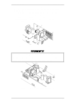
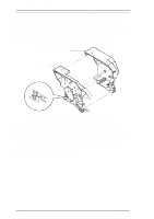
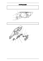
Disassembly and Assembly LQ-2070 Service Manual Assembly Notes Insert the timing belt properly into the 2 holding slots at the bottom of the CR assembly. Take up the timing belt slack between the two slots completely, as shown in the following figure. Insert the 2 oil pads into the proper positions in the CR assembly, as shown. If you remove the rear CR guide shaft along with the CR assembly, be sure to reinstall the rear CR guide shaft in the printer mechanism. The rear CR guide shaft has been drilled through the shaft near the right edge, and one side of the hole has a chamfered edge. This edge should be up. CR Assembly Timing Belt Figure 3-30 Inserting the Timing Belt Oil Pads Leaf Spring Bushing Carriage Assembly Figure 3-31 Installing the Oil Pads in the CR Assembly Right Frame Assembly Chamfered hole Figure 3-32 Assembling the Rear CR Guide Shaft 3-22 Rev.A
-
 1
1 -
2
-
3
-
4
-
5
-
6
-
7
-
8
-
9
-
10
-
11
-
12
-
13
-
14
-
15
-
16
-
17
-
18
-
19
-
20
-
21
-
22
-
23
-
24
-
25
-
26
-
27
-
28
-
29
-
30
-
31
-
32
-
33
-
34
-
35
-
36
-
37
-
38
-
39
-
40
-
41
-
42
-
43
-
44
-
45
-
46
-
47
-
48
-
49
-
50
-
51
-
52
-
53
-
54
-
55
-
56
-
57
-
58
-
59
-
60
-
61
-
62
-
63
-
64
-
65
-
66
-
67
-
68
-
69
-
70
-
71
-
72
-
73
-
74
-
75
-
76
-
77
-
78
-
79
-
80
-
81
-
82
-
83
-
84
-
85
-
86
-
87
-
88
-
89
-
90
-
91
-
92
-
93
-
94
-
 95
95 -
 96
96 -
 97
97 -
 98
98 -
 99
99 -
 100
100 -
 101
101 -
 102
102 -
 103
103 -
 104
104 -
 105
105 -
106
-
107
-
108
-
109
-
110
-
111
-
112
-
113
-
114
-
115
-
116
-
117
-
118
-
119
-
120
-
121
-
122
-
123
-
124
-
125
-
126
-
127
-
128
-
129
-
130
-
131
-
132
-
133
-
134
-
135
-
136
-
137
-
138
-
139
-
140
-
141
-
142
-
143
-
144
-
145
-
146
-
147
-
148
-
149
-
150
-
151
-
152
-
153
-
154
-
155
-
156
-
157
-
158
-
159
-
160
-
161
-
162
-
163
-
164
-
165
 |
 |
