Epson 2070 Service Manual - Page 30
Interface Specifications, Table 1-31 Pin Assignments for Forward Channel, Signal, Not connected.
 |
UPC - 010343812277
View all Epson 2070 manuals
Add to My Manuals
Save this manual to your list of manuals |
Page 30 highlights
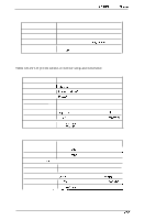
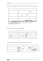
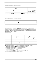
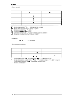
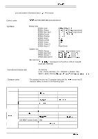
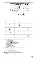
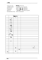
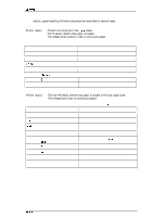
LQ-2070 Service Manual Product Description 1.3.2 Interface Specifications This printer provides a bidirectional 8-bit parallel interface and a Type B optional interface slot, standard. 1.3.2.1 Parallel Interface (Fotward Channel) q Transmission mode q Adaptable connector q Synchronization . Handshaking q Signal level 8-bit parallel, IEEE-P1284, compatibility mode 57-30360 (Amphenol) or equivalent STROBE P1.lk BUSY and ACI@lLG signals 'ITL compatible (IEEE-P1284 level 1. device) Table 1-31 Pin Assignments for Forward Channel Pin Signal Return No. Name GND pin 1 STROBE 19 2 DATA1 20 3 DATA2 21 4 DATA3 22 5 DATA4 23 6 DATA5 24 7 DATA6 25 8 DATA7 26 9 DATA8 27 10 ACKNLG 28 11 BUSY 29 , 12 PE 28 13 SLCT 28 14 AFXT 30 31 M 30 32 ERROR 29 36 SLIN 30 18 Logic H ---- 35 +5V ---- 17 Chassis ---- 16,33, 19-30 GND ---- 15,34 NC ---- In IOut In In In In In In In In In out out out out In In out In out Out --- ----- Function Description Strobe pulse. Input data is latched at falling edge of the signal Parallel input data to the printer bit O: LSB bit 1 bit 2 bit 3 bit 4 bit 5 bit 6 bit 7: MSB This signal (negative pulse) indicates the printer has received data and is ready to accept more data. This signal's HIGH level means the printer is not ready to accept data. This signal's HIGH level means the printer has a paper-out error. Always HIGH when the printer is powered on. Not used. This signal's negative pulse initializes printer. This signal's LOW level means the printer is in an error state. Not used. This line is pulled up to + 5 V through 3.9KQ resistor. This line is pulled up to +5 V through 3.3KQ resistor. Chassis GND. Signal GND. Not connected. Rev.A 1-21
-
 1
1 -
2
-
3
-
4
-
5
-
6
-
7
-
8
-
9
-
10
-
11
-
12
-
13
-
14
-
15
-
16
-
17
-
18
-
19
-
20
-
21
-
22
-
23
-
24
-
 25
25 -
 26
26 -
 27
27 -
 28
28 -
 29
29 -
 30
30 -
 31
31 -
 32
32 -
 33
33 -
 34
34 -
 35
35 -
36
-
37
-
38
-
39
-
40
-
41
-
42
-
43
-
44
-
45
-
46
-
47
-
48
-
49
-
50
-
51
-
52
-
53
-
54
-
55
-
56
-
57
-
58
-
59
-
60
-
61
-
62
-
63
-
64
-
65
-
66
-
67
-
68
-
69
-
70
-
71
-
72
-
73
-
74
-
75
-
76
-
77
-
78
-
79
-
80
-
81
-
82
-
83
-
84
-
85
-
86
-
87
-
88
-
89
-
90
-
91
-
92
-
93
-
94
-
95
-
96
-
97
-
98
-
99
-
100
-
101
-
102
-
103
-
104
-
105
-
106
-
107
-
108
-
109
-
110
-
111
-
112
-
113
-
114
-
115
-
116
-
117
-
118
-
119
-
120
-
121
-
122
-
123
-
124
-
125
-
126
-
127
-
128
-
129
-
130
-
131
-
132
-
133
-
134
-
135
-
136
-
137
-
138
-
139
-
140
-
141
-
142
-
143
-
144
-
145
-
146
-
147
-
148
-
149
-
150
-
151
-
152
-
153
-
154
-
155
-
156
-
157
-
158
-
159
-
160
-
161
-
162
-
163
-
164
-
165
 |
 |
