Epson 2070 Service Manual - Page 95
Engaging Gears 1
 |
UPC - 010343812277
View all Epson 2070 manuals
Add to My Manuals
Save this manual to your list of manuals |
Page 95 highlights
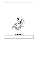
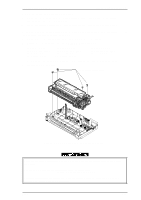
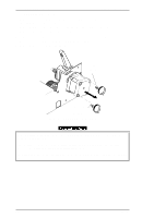
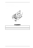
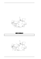
LQ-2070 Service Manual Disassembly and Assembly 2. Remove the right sub frame from the right frame assembly by disconnecting CN16 from the MAIN board assembly. 3. Remove the following 11 parts from the right frame assembly. 2 compression springs (200 g) 2 plain washers (8.2 x 0.5 x 15, S/Na) 2 spur gears (34.5 mm) 1 spur gear (34 mm) 1 combination gear (8 mm, 30 mm) 1 intermittent gear 1 spur gear (21 mm) 1 spur gear (27 mm) Assembly Notes C186 Adjust the bidirectional print alignment. Refer to Chapter 4. Mount the 11 parts above on the right frame assembly, as shown in the following figures. Compression Spring (200g) Plain Wahser (8.2x0.5x1.5S/Na) Spur Gear (21 mm) Spur Gear (34.5 mm) Compression Spring (200g) Plain Washer (8.2x0.5x1.5S\Na) Combination Gear (8mm/30mm) Intermittent Gear Spur Gear (27mm) Spur Gear (34.5mm) Spur Gear (34mm) Figure 3-21 Engaging Gears 1 Rev.A 3-17
-
 1
1 -
2
-
3
-
4
-
5
-
6
-
7
-
8
-
9
-
10
-
11
-
12
-
13
-
14
-
15
-
16
-
17
-
18
-
19
-
20
-
21
-
22
-
23
-
24
-
25
-
26
-
27
-
28
-
29
-
30
-
31
-
32
-
33
-
34
-
35
-
36
-
37
-
38
-
39
-
40
-
41
-
42
-
43
-
44
-
45
-
46
-
47
-
48
-
49
-
50
-
51
-
52
-
53
-
54
-
55
-
56
-
57
-
58
-
59
-
60
-
61
-
62
-
63
-
64
-
65
-
66
-
67
-
68
-
69
-
70
-
71
-
72
-
73
-
74
-
75
-
76
-
77
-
78
-
79
-
80
-
81
-
82
-
83
-
84
-
85
-
86
-
87
-
88
-
89
-
 90
90 -
 91
91 -
 92
92 -
 93
93 -
 94
94 -
 95
95 -
 96
96 -
 97
97 -
 98
98 -
 99
99 -
 100
100 -
101
-
102
-
103
-
104
-
105
-
106
-
107
-
108
-
109
-
110
-
111
-
112
-
113
-
114
-
115
-
116
-
117
-
118
-
119
-
120
-
121
-
122
-
123
-
124
-
125
-
126
-
127
-
128
-
129
-
130
-
131
-
132
-
133
-
134
-
135
-
136
-
137
-
138
-
139
-
140
-
141
-
142
-
143
-
144
-
145
-
146
-
147
-
148
-
149
-
150
-
151
-
152
-
153
-
154
-
155
-
156
-
157
-
158
-
159
-
160
-
161
-
162
-
163
-
164
-
165
 |
 |
