Epson 2070 Service Manual - Page 91
Removing the Printer Mechanism, Removing the Printer Mechanism
 |
UPC - 010343812277
View all Epson 2070 manuals
Add to My Manuals
Save this manual to your list of manuals |
Page 91 highlights
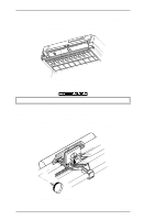
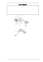
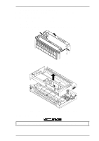
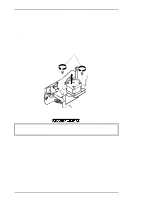
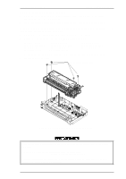
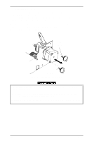
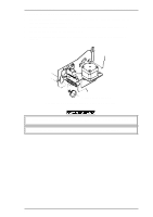
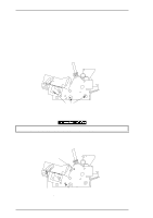
LQ-2070 Service Manual Disassembly and Assembly 3.2.9 Removing the Printer Mechanism 1. Remove the rear/front edge guide assembly, front cover, paper eject assembly, rear/front tractor units, and printer cover (see Section 3.2.1). 2. Remove the panel board assembly (see Section 3.2.2) and upper housing assembly (see Section 3.2.7). 3. Remove 3 CBS screws (3 x 4,F/Zn), 2 CBB screws (3 X 12,F/Zn) securing the upper shield plate over the main board, and remove the upper shield plate. 4. Remove 4 printer mechanism mounting screws securing the printer mechanism. 5. Disconnect the following connectors on the C186 MAIN board assembly: CN4 ( 3-pin, white) CN7 (4-pin, white FFC) CN10 (4-pin, blue) CN13 (2-pin, black) CN5 ( 3-pin, black) CN8 (17-pin, white FFC) CN11 (5-pin, blue) CN 16 (2-pin, yellow) CN6 ( 2-pin, white ) CN9 (15-pin, white FFC) CN12 (2-pin, white) g Disconnect the cables for CN10 and CN11 after releasing the connector locks by pulling up. 6. Remove the printer mechanism. Printer Mechanism Mounting Screws Figure 3-16 Removing the Printer Mechanism Assembly Notes Notice the connection for cables CN10 and CN11 and align the red colored cable to pin 1 of the connector. The tightening torque for the printer mechanism mounting screw = 0.98 Nm ~ 1.18 Nm (10 ~ 12 Kg - cm) Adjust the bidirectional print alignment. When the printer mechanism is replaced to new one, reset the TPE level. Refer to the Chapter 4. Rev.A 3-13
-
 1
1 -
2
-
3
-
4
-
5
-
6
-
7
-
8
-
9
-
10
-
11
-
12
-
13
-
14
-
15
-
16
-
17
-
18
-
19
-
20
-
21
-
22
-
23
-
24
-
25
-
26
-
27
-
28
-
29
-
30
-
31
-
32
-
33
-
34
-
35
-
36
-
37
-
38
-
39
-
40
-
41
-
42
-
43
-
44
-
45
-
46
-
47
-
48
-
49
-
50
-
51
-
52
-
53
-
54
-
55
-
56
-
57
-
58
-
59
-
60
-
61
-
62
-
63
-
64
-
65
-
66
-
67
-
68
-
69
-
70
-
71
-
72
-
73
-
74
-
75
-
76
-
77
-
78
-
79
-
80
-
81
-
82
-
83
-
84
-
85
-
 86
86 -
 87
87 -
 88
88 -
 89
89 -
 90
90 -
 91
91 -
 92
92 -
 93
93 -
 94
94 -
 95
95 -
 96
96 -
97
-
98
-
99
-
100
-
101
-
102
-
103
-
104
-
105
-
106
-
107
-
108
-
109
-
110
-
111
-
112
-
113
-
114
-
115
-
116
-
117
-
118
-
119
-
120
-
121
-
122
-
123
-
124
-
125
-
126
-
127
-
128
-
129
-
130
-
131
-
132
-
133
-
134
-
135
-
136
-
137
-
138
-
139
-
140
-
141
-
142
-
143
-
144
-
145
-
146
-
147
-
148
-
149
-
150
-
151
-
152
-
153
-
154
-
155
-
156
-
157
-
158
-
159
-
160
-
161
-
162
-
163
-
164
-
165
 |
 |
