Epson 2070 Service Manual - Page 87
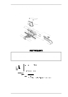
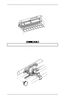
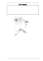
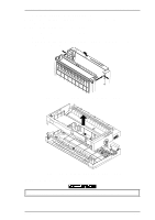
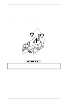
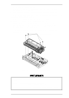
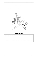
Mounting Position for the PW Sensor Assembly
 |
UPC - 010343812277
View all Epson 2070 manuals
Add to My Manuals
Save this manual to your list of manuals |
Page 87 highlights
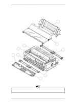
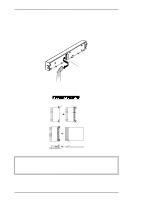
LQ-2070 Service Manual Disassembly and Assembly Assembly Notes Mount the PW sensor assembly onto the ribbon mask holder groove, aligning the bottom line of micro photo sensor to the bottom line of the groove. Whenever you remove the PW sensor assembly, clean the surface of the sensor by wiping it with a soft material. If the surface is not clean, abnormal operations may occur, such as printing on the platen surface. The tightening torque for the CB screw (2.5 × 5, F/Zn) = 0.08 ~ 0.12 Nm (0.8 ~ 0.12 Kg f-cm) When you replace the PW sensor assembly, reset the TPE level. Refer to Chapter 4. Micro Photo Sensor Bold Perforated line is the Groove. CB Screw ( 2.5X5 F/Zn) PW Sensor Assembly View of PW Sensor through Ribbon Mask Holder Ribbon Mask Holder Figure 3-10 Mounting Position for the PW Sensor Assembly Rev.A 3-9
-
 1
1 -
2
-
3
-
4
-
5
-
6
-
7
-
8
-
9
-
10
-
11
-
12
-
13
-
14
-
15
-
16
-
17
-
18
-
19
-
20
-
21
-
22
-
23
-
24
-
25
-
26
-
27
-
28
-
29
-
30
-
31
-
32
-
33
-
34
-
35
-
36
-
37
-
38
-
39
-
40
-
41
-
42
-
43
-
44
-
45
-
46
-
47
-
48
-
49
-
50
-
51
-
52
-
53
-
54
-
55
-
56
-
57
-
58
-
59
-
60
-
61
-
62
-
63
-
64
-
65
-
66
-
67
-
68
-
69
-
70
-
71
-
72
-
73
-
74
-
75
-
76
-
77
-
78
-
79
-
80
-
81
-
 82
82 -
 83
83 -
 84
84 -
 85
85 -
 86
86 -
 87
87 -
 88
88 -
 89
89 -
 90
90 -
 91
91 -
 92
92 -
93
-
94
-
95
-
96
-
97
-
98
-
99
-
100
-
101
-
102
-
103
-
104
-
105
-
106
-
107
-
108
-
109
-
110
-
111
-
112
-
113
-
114
-
115
-
116
-
117
-
118
-
119
-
120
-
121
-
122
-
123
-
124
-
125
-
126
-
127
-
128
-
129
-
130
-
131
-
132
-
133
-
134
-
135
-
136
-
137
-
138
-
139
-
140
-
141
-
142
-
143
-
144
-
145
-
146
-
147
-
148
-
149
-
150
-
151
-
152
-
153
-
154
-
155
-
156
-
157
-
158
-
159
-
160
-
161
-
162
-
163
-
164
-
165
 |
 |
