Epson 2070 Service Manual - Page 123
OVERVIEW, 2 TROUBLESHOOTING INFORMATION, 1. Printhead Coil Resistance Test Points - lq troubleshooting
 |
UPC - 010343812277
View all Epson 2070 manuals
Add to My Manuals
Save this manual to your list of manuals |
Page 123 highlights
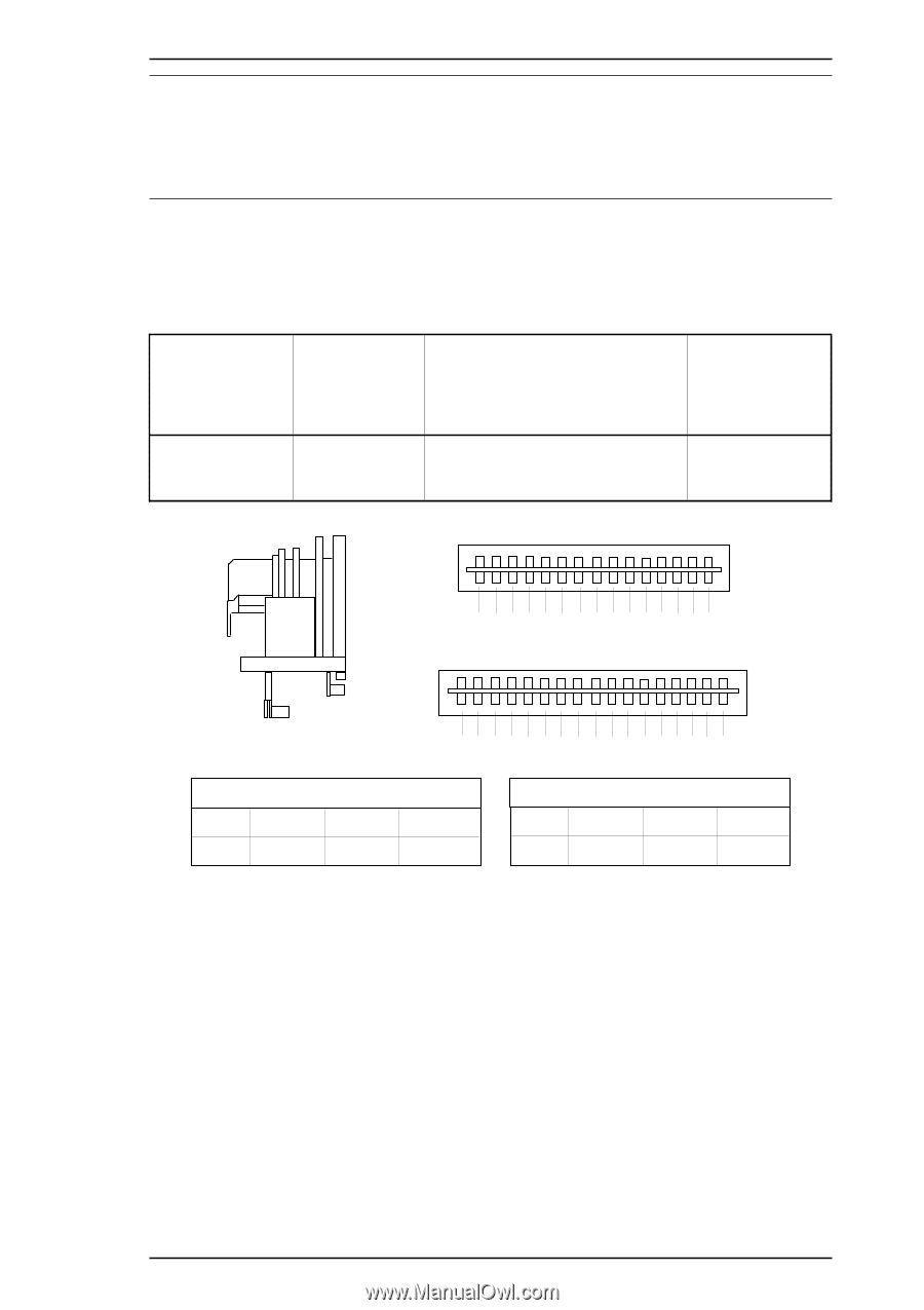
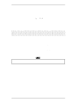
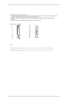
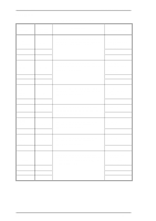
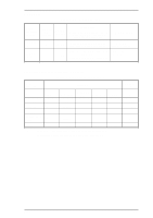
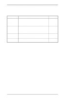
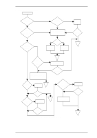
LQ-2070 Service Manual Troubleshooting 5.1 OVERVIEW This chapter contains flowcharts and checkpoint tables to help you troubleshoot the printer. Flowcharts let you isolate a faulty unit based on abnormal symptoms. The checkpoint tables let you identify the faulty part or unit by checking the values or ranges listed for each component. 5.2 TROUBLESHOOTING INFORMATION This section gives troubleshooting information to let you check test points for replaceable units. 5.2.1 Printhead 5-1. Printhead Coil Resistance Test Points Common Pin No. Refer to the following figure. Test Pin No. Test Method (Set meter to ohms. Disconnect the printhead after the printer is powered off.) Meter Reading Refer to the Place one lead on each pin and the 39.3 ± 10% Ω following figure. other lead on each common pin. ( at 25° C, 77° F) R R F 3 1 1 2 19 7 C 3 C 6 C 2 2 2 1 5 1 8 23 1 0 1 4 6 F 5 1 13 9 21 17 C5 C4 C1 24 20 12 8 16 T T 4 R COM. C2 C3 C6 Pin No, 2,6,10,18 3,7,11,15 14,22,19,23 F COM. C1 C4 C5 Pin No, 1,8,16,24 4,12,20,21 5,9,13,17 T : Thermistor terminal C1~C6 : Common terminal 1~24 : Wire number Figure 5-1 Printhead Connected Pin Alignment Rev.A 5-1
-
 1
1 -
2
-
3
-
4
-
5
-
6
-
7
-
8
-
9
-
10
-
11
-
12
-
13
-
14
-
15
-
16
-
17
-
18
-
19
-
20
-
21
-
22
-
23
-
24
-
25
-
26
-
27
-
28
-
29
-
30
-
31
-
32
-
33
-
34
-
35
-
36
-
37
-
38
-
39
-
40
-
41
-
42
-
43
-
44
-
45
-
46
-
47
-
48
-
49
-
50
-
51
-
52
-
53
-
54
-
55
-
56
-
57
-
58
-
59
-
60
-
61
-
62
-
63
-
64
-
65
-
66
-
67
-
68
-
69
-
70
-
71
-
72
-
73
-
74
-
75
-
76
-
77
-
78
-
79
-
80
-
81
-
82
-
83
-
84
-
85
-
86
-
87
-
88
-
89
-
90
-
91
-
92
-
93
-
94
-
95
-
96
-
97
-
98
-
99
-
100
-
101
-
102
-
103
-
104
-
105
-
106
-
107
-
108
-
109
-
110
-
111
-
112
-
113
-
114
-
115
-
116
-
117
-
 118
118 -
 119
119 -
 120
120 -
 121
121 -
 122
122 -
 123
123 -
 124
124 -
 125
125 -
 126
126 -
 127
127 -
 128
128 -
129
-
130
-
131
-
132
-
133
-
134
-
135
-
136
-
137
-
138
-
139
-
140
-
141
-
142
-
143
-
144
-
145
-
146
-
147
-
148
-
149
-
150
-
151
-
152
-
153
-
154
-
155
-
156
-
157
-
158
-
159
-
160
-
161
-
162
-
163
-
164
-
165
 |
 |