Epson 2070 Service Manual - Page 45
MAIN Board Assembly, Bridge, Trensformaer, Switching Regulator - lq driver
 |
UPC - 010343812277
View all Epson 2070 manuals
Add to My Manuals
Save this manual to your list of manuals |
Page 45 highlights
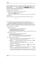
Product Description LQ-2070 Service Manual 1.6.1 C186 MAIN Board Assembly The C186 MAIN board consists of a TMP96C041AF CPU, an E05B13 gate array, a program/CG ROM, a PS-IWM, an EEPROM, etc. Head Driva TRANSISTOR IC 5 PS RAM ICI 1,14 PF Motor Driver TEA3718SDP 1 1 ~n D .H / \ IC12 CR Motor Driver SLA7024M IC 8 'CN2 for Option I I F EEPROM Figure 1-13 C186 MAIN Board Assembly 1.6.2 C166 PSB/PSE Board Assembly These boardshave two AC input voltage ratings: 120VAC (C166PSB) and230VAC (C166PSE). Both boards consist of a transformer, switcking FET, regulator IC, diode bridge, etc. The power supply board provides +5 VDC and +35 VDC for the main board and printer mechanism. F1 Q1 Fuse Switching FET I 1. /- w 'CIkDE,D l I I o Pcl Photo Coupler / / / / 1/ .- - C!!!!!o0 ; IC52 OP-amp n 1 1 \ r\ rA / DBI Diode Bridge Ti Trensformaer 1/51 Switching Regulator TL494CN Figure 1-14 C166 PSB/PSE Board Assembly 1-36 Rev.A
-
 1
1 -
2
-
3
-
4
-
5
-
6
-
7
-
8
-
9
-
10
-
11
-
12
-
13
-
14
-
15
-
16
-
17
-
18
-
19
-
20
-
21
-
22
-
23
-
24
-
25
-
26
-
27
-
28
-
29
-
30
-
31
-
32
-
33
-
34
-
35
-
36
-
37
-
38
-
39
-
 40
40 -
 41
41 -
 42
42 -
 43
43 -
 44
44 -
 45
45 -
 46
46 -
 47
47 -
 48
48 -
 49
49 -
 50
50 -
51
-
52
-
53
-
54
-
55
-
56
-
57
-
58
-
59
-
60
-
61
-
62
-
63
-
64
-
65
-
66
-
67
-
68
-
69
-
70
-
71
-
72
-
73
-
74
-
75
-
76
-
77
-
78
-
79
-
80
-
81
-
82
-
83
-
84
-
85
-
86
-
87
-
88
-
89
-
90
-
91
-
92
-
93
-
94
-
95
-
96
-
97
-
98
-
99
-
100
-
101
-
102
-
103
-
104
-
105
-
106
-
107
-
108
-
109
-
110
-
111
-
112
-
113
-
114
-
115
-
116
-
117
-
118
-
119
-
120
-
121
-
122
-
123
-
124
-
125
-
126
-
127
-
128
-
129
-
130
-
131
-
132
-
133
-
134
-
135
-
136
-
137
-
138
-
139
-
140
-
141
-
142
-
143
-
144
-
145
-
146
-
147
-
148
-
149
-
150
-
151
-
152
-
153
-
154
-
155
-
156
-
157
-
158
-
159
-
160
-
161
-
162
-
163
-
164
-
165
 |
 |
