Epson 2070 Service Manual - Page 79
OVERVIEW, 1.1 Precautions, 1.2 Tools, Table 3-1. Recommended Tools - lq cable connection
 |
UPC - 010343812277
View all Epson 2070 manuals
Add to My Manuals
Save this manual to your list of manuals |
Page 79 highlights
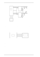
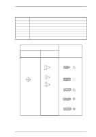
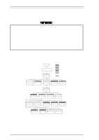
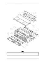
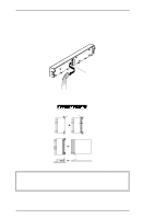
LQ-2070 Service Manual Disassembly and Assembly 3.1 OVERVIEW This section describes various points to note when disassembling and assembling the printer. 3.1.1 Precautions Follow the precautions below for disassembly or assembly. WARNING Before disassembling, assembling, or adjusting the printer, disconnect the power supply cable from the AC power socket. Failure to do so can cause physical injury. The power switch is wired in the secondary circuitry. Therefore, the printer's primary circuitry remains live even after the power switch is turned off. Never touch primary parts of the the power supply unit (including the heat sink) while the power supply cable is connected to the AC power socket. CAUTION To maintain efficient printer operation: • Use only recommended tools for maintenance work. • Use only recommended lubricants and adhesives (see Chapter 6). • Adjust the printer only in the manner described in this manual. 3.1.2 Tools Tables 3-1 and 3-2 list the tools recommended for disassembling, assembling, or adjusting the printer. Use only tools that meet these specifications. Table 3-1. Recommended Tools Tool Round-nose pliers Nippers Tweezers Soldering iron E-ring holder #2.5 Phillips screwdriver No. Standard screwdriver Thickness gauge Part No. B740400100 B740500100 B741000100 B740200100 B740800400 B743800200 B743000100 B776702201 Note: All tools are commercially available. Table 3-2. Equipment Required for Maintenance Description Multimeter Oscilloscope Specification -- 50 MHz Note: An oscilloscope is required only for servicers who repair to the component level. Rev.A 3-1
-
 1
1 -
2
-
3
-
4
-
5
-
6
-
7
-
8
-
9
-
10
-
11
-
12
-
13
-
14
-
15
-
16
-
17
-
18
-
19
-
20
-
21
-
22
-
23
-
24
-
25
-
26
-
27
-
28
-
29
-
30
-
31
-
32
-
33
-
34
-
35
-
36
-
37
-
38
-
39
-
40
-
41
-
42
-
43
-
44
-
45
-
46
-
47
-
48
-
49
-
50
-
51
-
52
-
53
-
54
-
55
-
56
-
57
-
58
-
59
-
60
-
61
-
62
-
63
-
64
-
65
-
66
-
67
-
68
-
69
-
70
-
71
-
72
-
73
-
 74
74 -
 75
75 -
 76
76 -
 77
77 -
 78
78 -
 79
79 -
 80
80 -
 81
81 -
 82
82 -
 83
83 -
 84
84 -
85
-
86
-
87
-
88
-
89
-
90
-
91
-
92
-
93
-
94
-
95
-
96
-
97
-
98
-
99
-
100
-
101
-
102
-
103
-
104
-
105
-
106
-
107
-
108
-
109
-
110
-
111
-
112
-
113
-
114
-
115
-
116
-
117
-
118
-
119
-
120
-
121
-
122
-
123
-
124
-
125
-
126
-
127
-
128
-
129
-
130
-
131
-
132
-
133
-
134
-
135
-
136
-
137
-
138
-
139
-
140
-
141
-
142
-
143
-
144
-
145
-
146
-
147
-
148
-
149
-
150
-
151
-
152
-
153
-
154
-
155
-
156
-
157
-
158
-
159
-
160
-
161
-
162
-
163
-
164
-
165
 |
 |
