Epson 2070 Service Manual - Page 49
PRINTER MECHANISM OPERATION, Ribbon Mask, Ribbon, Wire Resetting Spring, Actuating, Plate, Paper - lq printer driver
 |
UPC - 010343812277
View all Epson 2070 manuals
Add to My Manuals
Save this manual to your list of manuals |
Page 49 highlights
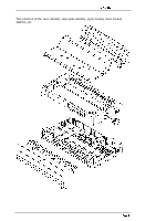
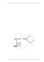
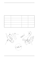
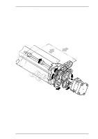
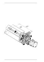
LQ-2070 Service Manual Operating Principles 2.1 PRINTER MECHANISM OPERATION This section describes the printer mechanism and explains how it works. 2.1.1 Printing Mechanism The printing mechanism is composed of the printhead, ink ribbon, and ribbon mask. The printhead is an 24-pin (12 pins × 2) head for impact dot printing. To improve the durability of the dot wires, they are arranged on the printhead in 2 columns. Each wire has its own drive coil, which causes the wire to move in and out of the printhead to print each dot. The four steps below describe how these driving wires work to print a single dot. 1. A drive signal, transmitted from the control circuit to the printhead driver circuit, is converted to the proper printhead driving voltage, which energizes a corresponding coil. The energized coil then causes the iron core to become magnetized. 2. The magnetic force draws the actuating plate toward the core, and the dot wire, which is connected to the core, rushes toward the platen. 3. When the dot wire impacts the platen, pressing against the ribbon and paper, it prints a dot. 4. When the driving voltage stops energizing the coil, the magnetic force from the iron core vanishes. The actuating plate returns to its original position (the position before coil was energized) with spring action. The dot wire also returns to its original position. The mechanism is equipped with a built-in thermistor for head temperature detection. The temperature detected by the thermistor is converted to an electric signal and fed back to the control circuit. The printhead is also used as a beeper. Head driving coils move all the dot wires back and forth at a frequency of 1.65 KHz for 90 ± 5 µsec without impacting the platen, so that the wires vibrate. The vibrating dot wires create the sound used for beep codes. Wire Resetting Spring Ribbon Stopper Dot Wire Ribbon Mask Paper Actuating Plate Iron Core Head Driving Coil Actuating Spring Platen Figure 2-1 Printhead Operation Principles Rev.A 2-1
-
 1
1 -
2
-
3
-
4
-
5
-
6
-
7
-
8
-
9
-
10
-
11
-
12
-
13
-
14
-
15
-
16
-
17
-
18
-
19
-
20
-
21
-
22
-
23
-
24
-
25
-
26
-
27
-
28
-
29
-
30
-
31
-
32
-
33
-
34
-
35
-
36
-
37
-
38
-
39
-
40
-
41
-
42
-
43
-
 44
44 -
 45
45 -
 46
46 -
 47
47 -
 48
48 -
 49
49 -
 50
50 -
 51
51 -
 52
52 -
 53
53 -
 54
54 -
55
-
56
-
57
-
58
-
59
-
60
-
61
-
62
-
63
-
64
-
65
-
66
-
67
-
68
-
69
-
70
-
71
-
72
-
73
-
74
-
75
-
76
-
77
-
78
-
79
-
80
-
81
-
82
-
83
-
84
-
85
-
86
-
87
-
88
-
89
-
90
-
91
-
92
-
93
-
94
-
95
-
96
-
97
-
98
-
99
-
100
-
101
-
102
-
103
-
104
-
105
-
106
-
107
-
108
-
109
-
110
-
111
-
112
-
113
-
114
-
115
-
116
-
117
-
118
-
119
-
120
-
121
-
122
-
123
-
124
-
125
-
126
-
127
-
128
-
129
-
130
-
131
-
132
-
133
-
134
-
135
-
136
-
137
-
138
-
139
-
140
-
141
-
142
-
143
-
144
-
145
-
146
-
147
-
148
-
149
-
150
-
151
-
152
-
153
-
154
-
155
-
156
-
157
-
158
-
159
-
160
-
161
-
162
-
163
-
164
-
165
 |
 |
