Epson 2070 Service Manual - Page 115
ADJUSTING AND RESETTING THE PRINTER, 2.1 Platen Gap Adjustment, Removing the Ribbon Mask
 |
UPC - 010343812277
View all Epson 2070 manuals
Add to My Manuals
Save this manual to your list of manuals |
Page 115 highlights
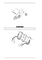
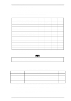
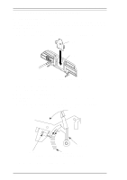
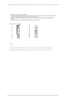
Adjustment LQ-2070 Service Manual 4.2 ADJUSTING AND RESETTING THE PRINTER 4.2.1 Platen Gap Adjustment If you have rotated or reassembled the rear CR guide shaft or parallelism adjustment bushing, or if printing is light or dark, even at the proper PG lever position, perform this adjustment with the printer in 3 positions: the 5th, 80th, and 130th columns. 1. Remove the printhead from the CR assembly (see Section 3.2.3). 2. Remove the ribbon mask from the ribbon mask holder using tweezers, as shown in the figure. Ribbon Mask Ribbon Mask Holder Figure 4-1 Removing the Ribbon Mask 3. Attach the printhead to the CR assembly again, tightening the 2 CBS screws (3 × 10, F/Zn). 4. Move the printhead to 5th column position. 5. Set the release lever to the FRICTION position. 6. Set the PG adjust lever to the second slot from rear of the printer mechanism as shown in the following illustration. 7. Loosen the hexagon nut (standard, M4) securing the PG adjust lever while setting the PG adjust lever to the second slot position from the rear of the printer mechanism. PG Adjust Lever PG SW PG Adjust Slot Figure 4-2 Setting the PG Adjust Lever 8. Insert the thickness gauge vertically between the printhead and platen. 4-2 Rev.A
-
 1
1 -
2
-
3
-
4
-
5
-
6
-
7
-
8
-
9
-
10
-
11
-
12
-
13
-
14
-
15
-
16
-
17
-
18
-
19
-
20
-
21
-
22
-
23
-
24
-
25
-
26
-
27
-
28
-
29
-
30
-
31
-
32
-
33
-
34
-
35
-
36
-
37
-
38
-
39
-
40
-
41
-
42
-
43
-
44
-
45
-
46
-
47
-
48
-
49
-
50
-
51
-
52
-
53
-
54
-
55
-
56
-
57
-
58
-
59
-
60
-
61
-
62
-
63
-
64
-
65
-
66
-
67
-
68
-
69
-
70
-
71
-
72
-
73
-
74
-
75
-
76
-
77
-
78
-
79
-
80
-
81
-
82
-
83
-
84
-
85
-
86
-
87
-
88
-
89
-
90
-
91
-
92
-
93
-
94
-
95
-
96
-
97
-
98
-
99
-
100
-
101
-
102
-
103
-
104
-
105
-
106
-
107
-
108
-
109
-
 110
110 -
 111
111 -
 112
112 -
 113
113 -
 114
114 -
 115
115 -
 116
116 -
 117
117 -
 118
118 -
 119
119 -
 120
120 -
121
-
122
-
123
-
124
-
125
-
126
-
127
-
128
-
129
-
130
-
131
-
132
-
133
-
134
-
135
-
136
-
137
-
138
-
139
-
140
-
141
-
142
-
143
-
144
-
145
-
146
-
147
-
148
-
149
-
150
-
151
-
152
-
153
-
154
-
155
-
156
-
157
-
158
-
159
-
160
-
161
-
162
-
163
-
164
-
165
 |
 |
