Epson 2070 Service Manual - Page 109
Removing the Paper Eject Assembly Cover, Removing the Gear Train Cover
 |
UPC - 010343812277
View all Epson 2070 manuals
Add to My Manuals
Save this manual to your list of manuals |
Page 109 highlights
LQ-2070 Service Manual Disassembly and Assembly 3.3.3 Removing the Paper Eject Assembly Cover 1. Remove the paper eject assembly cover by releasing 2 clips located along both edges of the paper eject assembly cover, as shown in the following figure. Gear Train Cover Figure 3-48 Removing the Gear Train Cover Assembly Note When attaching the paper eject assembly cover to the CSF unit, pay attention to the position of 2 pieces of thin plastic film glued on the reverse side of the paper eject assembly cover, as shown in the following figure. Combination Gear ( 25 mm/11mm) CSF Planetary Lever Assembly CSF Transmission Gauge Spring Plain Washer White Gear ( 22mm) Gear (22mm) Figure 3-49 Engaging 5 Gears Rev.A 3-31
-
 1
1 -
2
-
3
-
4
-
5
-
6
-
7
-
8
-
9
-
10
-
11
-
12
-
13
-
14
-
15
-
16
-
17
-
18
-
19
-
20
-
21
-
22
-
23
-
24
-
25
-
26
-
27
-
28
-
29
-
30
-
31
-
32
-
33
-
34
-
35
-
36
-
37
-
38
-
39
-
40
-
41
-
42
-
43
-
44
-
45
-
46
-
47
-
48
-
49
-
50
-
51
-
52
-
53
-
54
-
55
-
56
-
57
-
58
-
59
-
60
-
61
-
62
-
63
-
64
-
65
-
66
-
67
-
68
-
69
-
70
-
71
-
72
-
73
-
74
-
75
-
76
-
77
-
78
-
79
-
80
-
81
-
82
-
83
-
84
-
85
-
86
-
87
-
88
-
89
-
90
-
91
-
92
-
93
-
94
-
95
-
96
-
97
-
98
-
99
-
100
-
101
-
102
-
103
-
 104
104 -
 105
105 -
 106
106 -
 107
107 -
 108
108 -
 109
109 -
 110
110 -
 111
111 -
 112
112 -
 113
113 -
 114
114 -
115
-
116
-
117
-
118
-
119
-
120
-
121
-
122
-
123
-
124
-
125
-
126
-
127
-
128
-
129
-
130
-
131
-
132
-
133
-
134
-
135
-
136
-
137
-
138
-
139
-
140
-
141
-
142
-
143
-
144
-
145
-
146
-
147
-
148
-
149
-
150
-
151
-
152
-
153
-
154
-
155
-
156
-
157
-
158
-
159
-
160
-
161
-
162
-
163
-
164
-
165
 |
 |

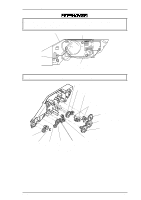
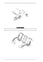
3.3.3 Removing the Paper Eject Assembly Cover
1.
Remove the paper eject assembly cover by releasing 2 clips located along both edges of the paper
eject assembly cover, as shown in the following figure.
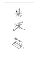
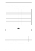
When attaching the paper eject assembly cover to the CSF unit, pay attention to the position of
2
pieces of thin plastic film glued on the reverse side of the paper eject assembly cover, as shown in
the following figure.
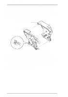
Gear Train Cover
Figure 3-48 Removing the Gear Train Cover
Gear (22mm)
White Gear ( 22mm)
Combination Gear ( 25 mm/11mm)
CSF Planetary Lever Assembly
CSF Transmission Gauge
Spring
Plain Washer
Figure 3-49 Engaging 5 Gears
LQ-2070 Service Manual
Disassembly and Assembly
Rev.A
3-31