Epson 5550C User Manual - Page 167
Computer In and Computer Out connector pin assignments
 |
UPC - 010343820807
View all Epson 5550C manuals
Add to My Manuals
Save this manual to your list of manuals |
Page 167 highlights
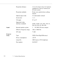
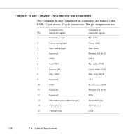
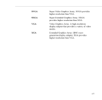
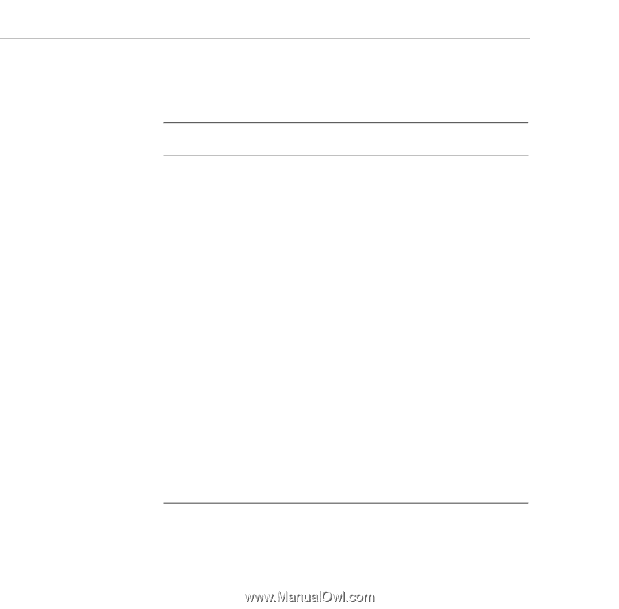
Computer In and Computer Out connector pin assignments The Computer In and Computer Out connectors are female video RGB, 15-pin micro-D-style connectors. The pin assignments are: Computer Out Pin connector signals 1 Red analog input 2 Green analog input 3 Blue analog input 4 Reserved Computer In connector signals Red video Green video Blue video Monitor (ID bit 2) 5 GND GND 6 Red GND Red video GND 7 Green GND Green video GND 8 Blue GND Blue video GND 9 Reserved +5 V 10 GND Synchronous GND 11 Reserved Monitor (ID bit 0) 12 Reserved SDA 13 Horizontal sync/composite sync Horizontal sync 14 Vertical sync Vertical sync 15 Vertical sync (SCL) 154 7 • Technical Specifications
-
 1
1 -
2
-
3
-
4
-
5
-
6
-
7
-
8
-
9
-
10
-
11
-
12
-
13
-
14
-
15
-
16
-
17
-
18
-
19
-
20
-
21
-
22
-
23
-
24
-
25
-
26
-
27
-
28
-
29
-
30
-
31
-
32
-
33
-
34
-
35
-
36
-
37
-
38
-
39
-
40
-
41
-
42
-
43
-
44
-
45
-
46
-
47
-
48
-
49
-
50
-
51
-
52
-
53
-
54
-
55
-
56
-
57
-
58
-
59
-
60
-
61
-
62
-
63
-
64
-
65
-
66
-
67
-
68
-
69
-
70
-
71
-
72
-
73
-
74
-
75
-
76
-
77
-
78
-
79
-
80
-
81
-
82
-
83
-
84
-
85
-
86
-
87
-
88
-
89
-
90
-
91
-
92
-
93
-
94
-
95
-
96
-
97
-
98
-
99
-
100
-
101
-
102
-
103
-
104
-
105
-
106
-
107
-
108
-
109
-
110
-
111
-
112
-
113
-
114
-
115
-
116
-
117
-
118
-
119
-
120
-
121
-
122
-
123
-
124
-
125
-
126
-
127
-
128
-
129
-
130
-
131
-
132
-
133
-
134
-
135
-
136
-
137
-
138
-
139
-
140
-
141
-
142
-
143
-
144
-
145
-
146
-
147
-
148
-
149
-
150
-
151
-
152
-
153
-
154
-
155
-
156
-
157
-
158
-
159
-
160
-
161
-
 162
162 -
 163
163 -
 164
164 -
 165
165 -
 166
166 -
 167
167 -
 168
168 -
 169
169 -
 170
170 -
 171
171 -
 172
172 -
173
-
174
-
175
-
176
-
177
-
178
 |
 |
7
•
Technical Specifications
154
Computer In and Computer Out connector pin assignments
The Computer In and Computer Out connectors are female video
RGB, 15-pin micro-D-style connectors. The pin assignments are:
Pin
Computer Out
connector signals
Computer In
connector signals
1
Red analog input
Red video
2
Green analog input
Green video
3
Blue analog input
Blue video
4
Reserved
Monitor (ID bit 2)
5
GND
GND
6
Red GND
Red video GND
7
Green GND
Green video GND
8
Blue GND
Blue video GND
9
Reserved
+5 V
10
GND
Synchronous GND
11
Reserved
Monitor (ID bit 0)
12
Reserved
SDA
13
Horizontal sync/composite sync
Horizontal sync
14
Vertical sync
Vertical sync
15
Vertical sync
(SCL)