Epson ActionTower 8100 User Manual - Page 89
Remove any option cards that are blocking access to
 |
View all Epson ActionTower 8100 manuals
Add to My Manuals
Save this manual to your list of manuals |
Page 89 highlights
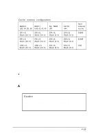
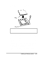
You must install chips in one of the configurations in the table below (each bank contains four cache memory sockets). Cache memory configurations BANK 0 BANK 1 Tag SRAM U33, 34, 35, 36 U40,41,42,43 U20 32K x 8, 28-pin (3.3 V) 32K x 8, 28-pin (3.3 V) 32K x 8, 28-pin (5 V) 64K x 8, 28-pin (3.3 V) 64K x 8, 28-pin (3.3 V) 32K x 8, 28-pin (5 V) 128K x 8, 32-pin (3.3 V) 128K x 8, 32-pin (3.3 V) 32K x 8, 28-pin (5 V) ALT bit U44 32K x 8, 28-pin (5 V) 32K x 8, 28-pin (5 V) 32K x 8, 28-pin (5 V) Total external cache 256KB 512KB 1MB Follow these steps to install external cache on the slim line computer: First remove the internal drive mounting bracket in your computer; see "Removing the Drive Mounting Bracket" in Chapter 5 for instructions. Locate the external cache memory sockets as shown in the illustration under "Locating the System Board Components." Remove any option cards that are blocking access to the sockets; see "Removing an Option Card" for instructions. Caution To avoid generating static electricity and damaging the cache chips, ground yourself by touching the metal surface on the inside of the computer's back panel. Then remain as stationary as possible while you install them. Installing and Removing Options 4-25
-
 1
1 -
2
-
3
-
4
-
5
-
6
-
7
-
8
-
9
-
10
-
11
-
12
-
13
-
14
-
15
-
16
-
17
-
18
-
19
-
20
-
21
-
22
-
23
-
24
-
25
-
26
-
27
-
28
-
29
-
30
-
31
-
32
-
33
-
34
-
35
-
36
-
37
-
38
-
39
-
40
-
41
-
42
-
43
-
44
-
45
-
46
-
47
-
48
-
49
-
50
-
51
-
52
-
53
-
54
-
55
-
56
-
57
-
58
-
59
-
60
-
61
-
62
-
63
-
64
-
65
-
66
-
67
-
68
-
69
-
70
-
71
-
72
-
73
-
74
-
75
-
76
-
77
-
78
-
79
-
80
-
81
-
82
-
83
-
 84
84 -
 85
85 -
 86
86 -
 87
87 -
 88
88 -
 89
89 -
 90
90 -
 91
91 -
 92
92 -
 93
93 -
 94
94 -
95
-
96
-
97
-
98
-
99
-
100
-
101
-
102
-
103
-
104
-
105
-
106
-
107
-
108
-
109
-
110
-
111
-
112
-
113
-
114
-
115
-
116
-
117
-
118
-
119
-
120
-
121
-
122
-
123
-
124
-
125
-
126
-
127
-
128
-
129
-
130
-
131
-
132
-
133
-
134
-
135
-
136
-
137
-
138
-
139
-
140
-
141
-
142
-
143
-
144
-
145
-
146
-
147
-
148
-
149
-
150
-
151
-
152
-
153
-
154
-
155
-
156
-
157
-
158
-
159
-
160
-
161
-
162
-
163
-
164
-
165
-
166
-
167
-
168
-
169
-
170
-
171
-
172
-
173
-
174
-
175
-
176
-
177
-
178
-
179
-
180
-
181
-
182
-
183
-
184
-
185
-
186
-
187
 |
 |
