Epson ActionTower 8100 User Manual - Page 90
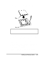
Gently press the chip halfway into the socket to make sure, the corresponding notch on the socket.
 |
View all Epson ActionTower 8100 manuals
Add to My Manuals
Save this manual to your list of manuals |
Page 90 highlights
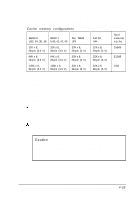
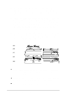
4. Remove the cache memory chips in sockets U33-U36 and U40-U43. Use a chip remover or wedge a small screwdriver between the sockets and the chips until you can remove the chips. 5. Inspect each cache memory chip you are going to install; the pins should point inward at slightly less than a 90° angle. If any of the pins are bent or crooked, straighten them gently with your fingers or with small tweezers to align them with the other pins. Be careful when you do this; the pins are fragile and can break off easily. 6. Position one of the cache chips over the first socket as shown below, aligning the pins on the chip with the holes in the socket. Align the small notch on the end of the chip with the corresponding notch on the socket. U44 U40 U41 U42 U43 Gently press the chip halfway into the socket (to make sure it is correctly aligned). If the chip goes in at an angle, remove it and try again. When the chip is properly positioned, push down firmly on both ends of the chip to make sure it is well-seated. Repeat steps 5 through 7 for each of the remaining chips. 4-26 Installing and Removing Options
-
 1
1 -
2
-
3
-
4
-
5
-
6
-
7
-
8
-
9
-
10
-
11
-
12
-
13
-
14
-
15
-
16
-
17
-
18
-
19
-
20
-
21
-
22
-
23
-
24
-
25
-
26
-
27
-
28
-
29
-
30
-
31
-
32
-
33
-
34
-
35
-
36
-
37
-
38
-
39
-
40
-
41
-
42
-
43
-
44
-
45
-
46
-
47
-
48
-
49
-
50
-
51
-
52
-
53
-
54
-
55
-
56
-
57
-
58
-
59
-
60
-
61
-
62
-
63
-
64
-
65
-
66
-
67
-
68
-
69
-
70
-
71
-
72
-
73
-
74
-
75
-
76
-
77
-
78
-
79
-
80
-
81
-
82
-
83
-
84
-
 85
85 -
 86
86 -
 87
87 -
 88
88 -
 89
89 -
 90
90 -
 91
91 -
 92
92 -
 93
93 -
 94
94 -
 95
95 -
96
-
97
-
98
-
99
-
100
-
101
-
102
-
103
-
104
-
105
-
106
-
107
-
108
-
109
-
110
-
111
-
112
-
113
-
114
-
115
-
116
-
117
-
118
-
119
-
120
-
121
-
122
-
123
-
124
-
125
-
126
-
127
-
128
-
129
-
130
-
131
-
132
-
133
-
134
-
135
-
136
-
137
-
138
-
139
-
140
-
141
-
142
-
143
-
144
-
145
-
146
-
147
-
148
-
149
-
150
-
151
-
152
-
153
-
154
-
155
-
156
-
157
-
158
-
159
-
160
-
161
-
162
-
163
-
164
-
165
-
166
-
167
-
168
-
169
-
170
-
171
-
172
-
173
-
174
-
175
-
176
-
177
-
178
-
179
-
180
-
181
-
182
-
183
-
184
-
185
-
186
-
187
 |
 |
