Epson ActionTower 8400 User Manual - Page 97
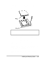
an IDE CD-ROM, Drives in the Slimline Computer
 |
View all Epson ActionTower 8400 manuals
Add to My Manuals
Save this manual to your list of manuals |
Page 97 highlights
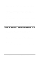
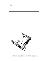
Note Use the primary IDE interface to connect only IDE hard disk drives. You must connect any other type of IDE devices to the secondary IDE interface. Never connect an IDE CD-ROM drive to the same interface used by an IDE hard disk drive. Before you install a drive, identify pin 1 on the drive connector so you know where it is when you connect the drive cable. On a hard disk drive, turn it over so you can see the circuit board, as shown below. Locate the side of the drive connector containing pin 1, indicated by a "1" printed on the connector or the board (a "2" may be printed beside the opposite row of pins to indicate the side of the connector containing pin 1). On a CD-ROM drive, check for a label identifying pin 1. For hard disk drives, you may also want to make a note of the drive parameters (such as cylinders, heads, etc.), in case the SETUP auto-sensing feature cannot detect them when you configure the drive. The parameters may be listed on a drive label or in the drive documentation. Installing and Removing Drives in the Slimline Computer 5 - 3
-
 1
1 -
2
-
3
-
4
-
5
-
6
-
7
-
8
-
9
-
10
-
11
-
12
-
13
-
14
-
15
-
16
-
17
-
18
-
19
-
20
-
21
-
22
-
23
-
24
-
25
-
26
-
27
-
28
-
29
-
30
-
31
-
32
-
33
-
34
-
35
-
36
-
37
-
38
-
39
-
40
-
41
-
42
-
43
-
44
-
45
-
46
-
47
-
48
-
49
-
50
-
51
-
52
-
53
-
54
-
55
-
56
-
57
-
58
-
59
-
60
-
61
-
62
-
63
-
64
-
65
-
66
-
67
-
68
-
69
-
70
-
71
-
72
-
73
-
74
-
75
-
76
-
77
-
78
-
79
-
80
-
81
-
82
-
83
-
84
-
85
-
86
-
87
-
88
-
89
-
90
-
91
-
 92
92 -
 93
93 -
 94
94 -
 95
95 -
 96
96 -
 97
97 -
 98
98 -
 99
99 -
 100
100 -
 101
101 -
 102
102 -
103
-
104
-
105
-
106
-
107
-
108
-
109
-
110
-
111
-
112
-
113
-
114
-
115
-
116
-
117
-
118
-
119
-
120
-
121
-
122
-
123
-
124
-
125
-
126
-
127
-
128
-
129
-
130
-
131
-
132
-
133
-
134
-
135
-
136
-
137
-
138
-
139
-
140
-
141
-
142
-
143
-
144
-
145
-
146
-
147
-
148
-
149
-
150
-
151
-
152
-
153
-
154
-
155
-
156
-
157
-
158
-
159
-
160
-
161
-
162
-
163
-
164
-
165
-
166
-
167
-
168
-
169
-
170
-
171
-
172
-
173
-
174
-
175
-
176
-
177
-
178
-
179
-
180
-
181
-
182
-
183
-
184
-
185
-
186
-
187
 |
 |
