Epson FX-85 User Manual - Page 89
Data Transfer Sequence, Interface timing, Signal relationships
 |
View all Epson FX-85 manuals
Add to My Manuals
Save this manual to your list of manuals |
Page 89 highlights
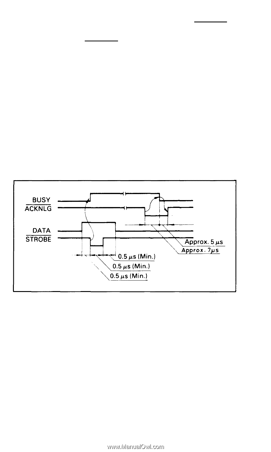
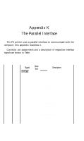
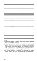
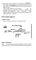
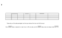
4. Data transfer must be carried out by observing the ACKNLG or BUSY signal. (Data transfer to this printer can be carried out only after receipt of the ACKNLG signal or when the level of the BUSY signal is LOW.) 5. Under normal conditions, printer cable pins 11, 12, and 32 are activated when the paper-out condition is detected. The ESCape"8" code disables pins 11 and 32, but not pin 12. Those computers that monitor pin 12 halt printing when the paper is out, making ESCape"8" ineffective. Data Transfer Sequence Interface timing Figure K-1 shows the timing for the parallel interface. Figure K-1. Parallel interface timing Signal relationships Table K-2 shows the way data entry is handled in the On-Line and Off-Line states by showing the relationships between seven signal sets. 335
-
 1
1 -
2
-
3
-
4
-
5
-
6
-
7
-
8
-
9
-
10
-
11
-
12
-
13
-
14
-
15
-
16
-
17
-
18
-
19
-
20
-
21
-
22
-
23
-
24
-
25
-
26
-
27
-
28
-
29
-
30
-
31
-
32
-
33
-
34
-
35
-
36
-
37
-
38
-
39
-
40
-
41
-
42
-
43
-
44
-
45
-
46
-
47
-
48
-
49
-
50
-
51
-
52
-
53
-
54
-
55
-
56
-
57
-
58
-
59
-
60
-
61
-
62
-
63
-
64
-
65
-
66
-
67
-
68
-
69
-
70
-
71
-
72
-
73
-
74
-
75
-
76
-
77
-
78
-
79
-
80
-
81
-
82
-
83
-
 84
84 -
 85
85 -
 86
86 -
 87
87 -
 88
88 -
 89
89 -
 90
90 -
 91
91 -
 92
92 -
 93
93 -
 94
94 -
95
-
96
-
97
-
98
-
99
-
100
-
101
-
102
-
103
-
104
-
105
-
106
-
107
-
108
 |
 |