Foxconn FlamingBlade GTI English Manual. - Page 23
Floppy Disk Drive Connector : FLOPPY1, USB Connectors : F_USB1/2, IDE Connector : PIDE1, pin ATX 12
 |
View all Foxconn FlamingBlade GTI manuals
Add to My Manuals
Save this manual to your list of manuals |
Page 23 highlights
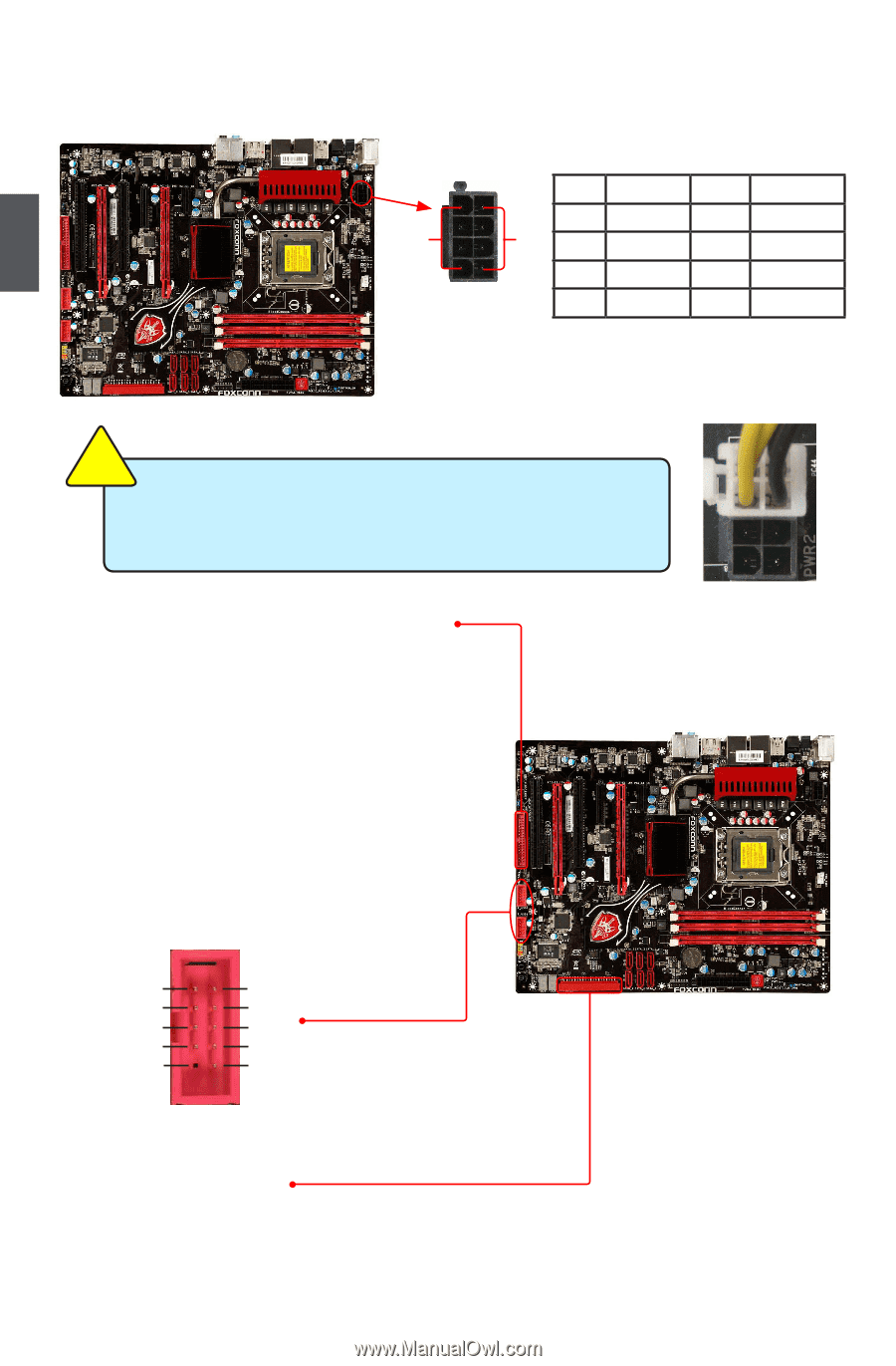
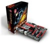
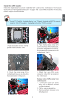
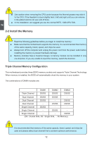
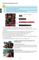
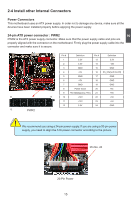
8-pin ATX 12 V Power Connector : PWR1 The 8-pin ATX 12V power supply connects to PWR1 and provides power to the CPU. 2 CAUTION +12V 51 Pin # 1 GND 2 3 84 4 PWR1 Definition GND GND GND GND Pin # 5 6 7 8 Definition +12V +12V +12V +12V Connect a 4-pin power plug ! We recommend you using an 8-pin ATX 12V power supply. If you are using a 4-pin power supply, you need to align the ATX power connector according to the picture on the right. Floppy Disk Drive Connector : FLOPPY1 This motherboard includes a standard floppy disk drive(FDD) connector, supporting 360KB, 720KB, 1.2MB, 1.44MB, and 2.88MB FDDs. USB Connectors : F_USB1/2 In addition to the eight USB ports on the rear panel, this product also provides two 10-pin USB connectors on its motherboard. By connecting through USB cables with them, user can quickly expand another four USB ports on the front panel . 12 VCC DD+ GND EMPTY VCC DD+ GND NC 9 10 F_USB 1/2 IDE Connector : PIDE1 With the provided Ultra DMA IDE ribbon cable, you can connect to any IDE type of hard disk and CD/ DVD ROM/RW drive. 16
-
 1
1 -
2
-
3
-
4
-
5
-
6
-
7
-
8
-
9
-
10
-
11
-
12
-
13
-
14
-
15
-
16
-
17
-
 18
18 -
 19
19 -
 20
20 -
 21
21 -
 22
22 -
 23
23 -
 24
24 -
 25
25 -
 26
26 -
 27
27 -
 28
28 -
29
-
30
-
31
-
32
-
33
-
34
-
35
-
36
-
37
-
38
-
39
-
40
-
41
-
42
-
43
-
44
-
45
-
46
-
47
-
48
-
49
-
50
-
51
-
52
-
53
-
54
-
55
-
56
-
57
-
58
-
59
-
60
-
61
-
62
-
63
-
64
-
65
-
66
-
67
-
68
-
69
-
70
-
71
-
72
-
73
-
74
-
75
-
76
-
77
-
78
-
79
-
80
-
81
-
82
-
83
-
84
-
85
-
86
-
87
-
88
-
89
-
90
-
91
-
92
-
93
-
94
-
95
-
96
-
97
-
98
-
99
-
100
-
101
-
102
-
103
-
104
-
105
-
106
-
107
-
108
-
109
-
110
-
111
-
112
-
113
-
114
-
115
-
116
-
117
-
118
-
119
-
120
-
121
-
122
 |
 |