HP 5310m HP ProBook 5310m Notebook PC - Maintenance and Service Guide - Page 79
Remove the two Torx T8M2.5×4.0 screws
 |
UPC - 884962601266
View all HP 5310m manuals
Add to My Manuals
Save this manual to your list of manuals |
Page 79 highlights
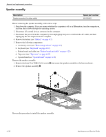
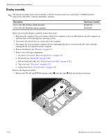
Removal and replacement procedures Ä CAUTION: Support the display assembly when removing the following screws. Failure to support the display assembly can result in damage to the display assembly and other computer components. 2. Remove the two Torx T8M2.5×4.0 screws 1 and the Torx T8M2.5×9.0 screw 2 that secure the display assembly to the base enclosure. 3. Lift the display assembly 3 straight up and remove it. 4. If it is necessary to replace the display bezel or any of the display assembly internal components: a. Remove the two rubber screw covers 1 and the two Phillips PM2.5×5.0 screws 2 that secure the display bezel to the display enclosure. Maintenance and Service Guide 4-43
-
 1
1 -
2
-
3
-
4
-
5
-
6
-
7
-
8
-
9
-
10
-
11
-
12
-
13
-
14
-
15
-
16
-
17
-
18
-
19
-
20
-
21
-
22
-
23
-
24
-
25
-
26
-
27
-
28
-
29
-
30
-
31
-
32
-
33
-
34
-
35
-
36
-
37
-
38
-
39
-
40
-
41
-
42
-
43
-
44
-
45
-
46
-
47
-
48
-
49
-
50
-
51
-
52
-
53
-
54
-
55
-
56
-
57
-
58
-
59
-
60
-
61
-
62
-
63
-
64
-
65
-
66
-
67
-
68
-
69
-
70
-
71
-
72
-
73
-
 74
74 -
 75
75 -
 76
76 -
 77
77 -
 78
78 -
 79
79 -
 80
80 -
 81
81 -
 82
82 -
 83
83 -
 84
84 -
85
-
86
-
87
-
88
-
89
-
90
-
91
-
92
-
93
-
94
-
95
-
96
-
97
-
98
-
99
-
100
-
101
-
102
-
103
-
104
-
105
-
106
-
107
-
108
-
109
-
110
-
111
-
112
-
113
-
114
-
115
-
116
-
117
-
118
-
119
-
120
-
121
-
122
-
123
-
124
-
125
-
126
-
127
-
128
-
129
-
130
-
131
-
132
-
133
-
134
-
135
-
136
-
137
-
138
-
139
-
140
-
141
-
142
-
143
-
144
-
145
-
146
-
147
-
148
-
149
-
150
-
151
-
152
-
153
-
154
-
155
-
156
-
157
 |
 |
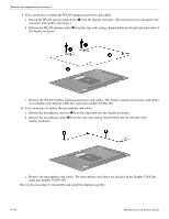
Removal and replacement procedures
Maintenance and Service Guide
4–43
Ä
CAUTION:
Support the display assembly when removing the following screws. Failure to support the display
assembly can result in damage to the display assembly and other computer components.
2. Remove the two Torx T8M2.5×4.0 screws
1
and the Torx T8M2.5×9.0 screw
2
that secure the display
assembly to the base enclosure.
3. Lift the display assembly
3
straight up and remove it.
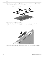
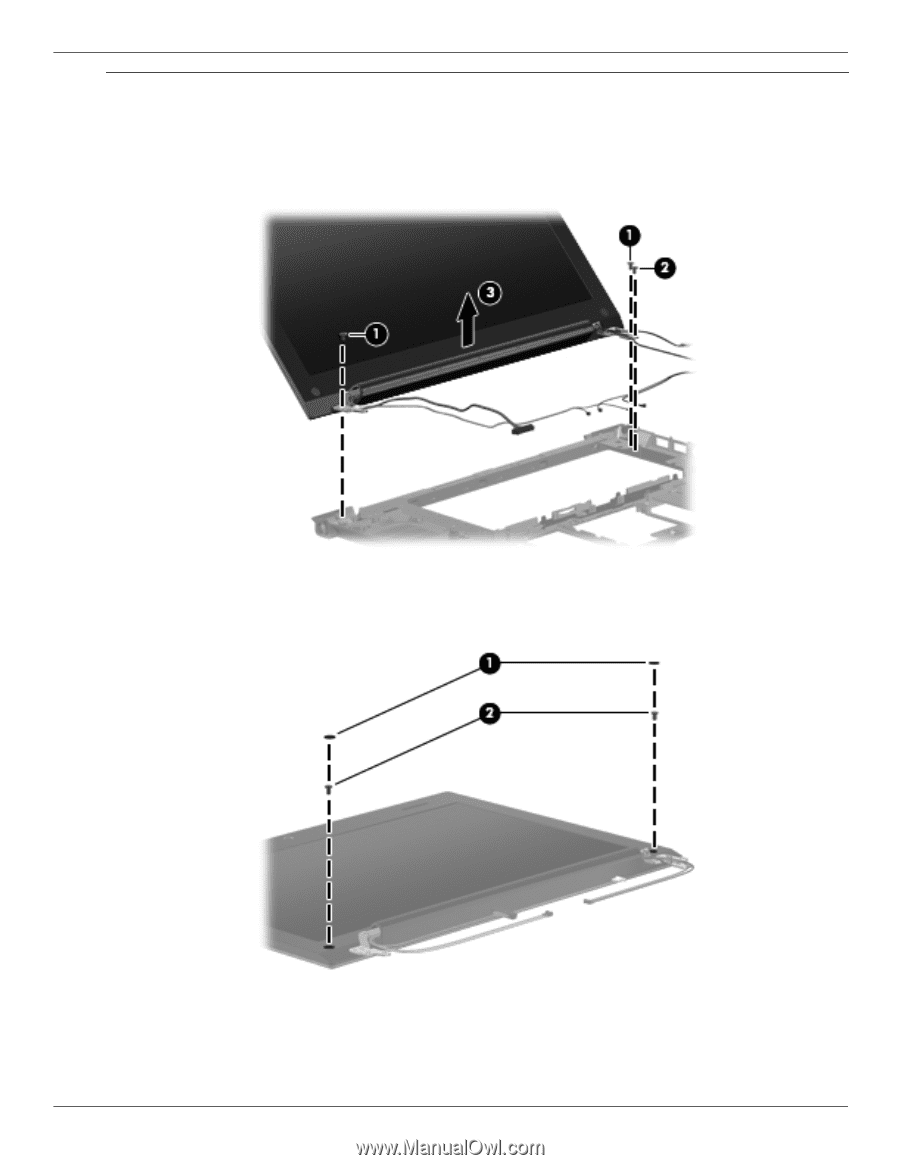
4. If it is necessary to replace the display bezel or any of the display assembly internal components:
a.
Remove the two rubber screw covers
1
and the two Phillips PM2.5×5.0 screws
2
that secure the display
bezel to the display enclosure.