HP 5310m HP ProBook 5310m Notebook PC - Maintenance and Service Guide - Page 84
If it is necessary to replace the microphones and cables, are included in the Display Cable Kit
 |
UPC - 884962601266
View all HP 5310m manuals
Add to My Manuals
Save this manual to your list of manuals |
Page 84 highlights
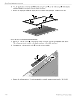
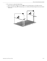
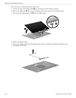
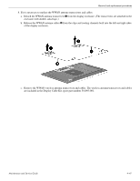
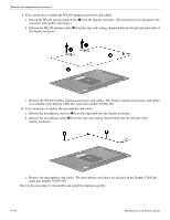
Removal and replacement procedures 9. If it is necessary to replace the WLAN antenna transceivers and cables: a. Detach the WLAN antenna transceivers 1 from the display enclosure. (The transceivers are attached to the enclosure with double-sided tape.) b. Release the WLAN antenna cables 2 from the clips and routing channel built into the left and right sides of the display enclosure. c. Remove the WLAN wireless antenna transceivers and cables. The wireless antenna transceivers and cables are included in the Display Cable Kit, spare part number 581093-001. 10. If it is necessary to replace the microphones and cables: a. Release the microphone receivers 1 from the clips built into the display enclosure. b. Release the microphone cables 2 from the clips and routing channel built into the left side of the display enclosure. c. Remove the microphones and cables. The microphones and cables are included in the Display Cable Kit, spare part number 581093-001. Reverse this procedure to reassemble and install the display assembly. 4-48 Maintenance and Service Guide
-
 1
1 -
2
-
3
-
4
-
5
-
6
-
7
-
8
-
9
-
10
-
11
-
12
-
13
-
14
-
15
-
16
-
17
-
18
-
19
-
20
-
21
-
22
-
23
-
24
-
25
-
26
-
27
-
28
-
29
-
30
-
31
-
32
-
33
-
34
-
35
-
36
-
37
-
38
-
39
-
40
-
41
-
42
-
43
-
44
-
45
-
46
-
47
-
48
-
49
-
50
-
51
-
52
-
53
-
54
-
55
-
56
-
57
-
58
-
59
-
60
-
61
-
62
-
63
-
64
-
65
-
66
-
67
-
68
-
69
-
70
-
71
-
72
-
73
-
74
-
75
-
76
-
77
-
78
-
 79
79 -
 80
80 -
 81
81 -
 82
82 -
 83
83 -
 84
84 -
 85
85 -
 86
86 -
 87
87 -
 88
88 -
 89
89 -
90
-
91
-
92
-
93
-
94
-
95
-
96
-
97
-
98
-
99
-
100
-
101
-
102
-
103
-
104
-
105
-
106
-
107
-
108
-
109
-
110
-
111
-
112
-
113
-
114
-
115
-
116
-
117
-
118
-
119
-
120
-
121
-
122
-
123
-
124
-
125
-
126
-
127
-
128
-
129
-
130
-
131
-
132
-
133
-
134
-
135
-
136
-
137
-
138
-
139
-
140
-
141
-
142
-
143
-
144
-
145
-
146
-
147
-
148
-
149
-
150
-
151
-
152
-
153
-
154
-
155
-
156
-
157
 |
 |
