HP 5310m HP ProBook 5310m Notebook PC - Maintenance and Service Guide - Page 80
as far from the display enclosure as the webcam module cable allows., Release the webcam module
 |
UPC - 884962601266
View all HP 5310m manuals
Add to My Manuals
Save this manual to your list of manuals |
Page 80 highlights
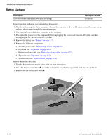
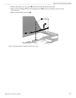
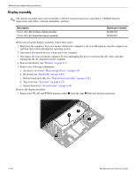
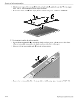
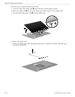
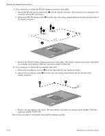
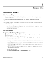
Removal and replacement procedures b. Flex the inside edges of the top edge 1, the left and right sides 2, and the bottom edge 3 of the display bezel until the bezel disengages from the display enclosure. c. Remove the display bezel 4. The display bezel is available using spare part number 581092-001. 5. If it is necessary to replace the webcam module: a. Release the webcam module 1 as far from the display enclosure as the webcam module cable allows. (The webcam module is attached to the display enclosure with double-sided tape.) b. Disconnect the webcam module cable 2 from the webcam module. c. Remove the webcam module. The webcam module is available using spare part number 581106-001. 4-44 Maintenance and Service Guide
-
 1
1 -
2
-
3
-
4
-
5
-
6
-
7
-
8
-
9
-
10
-
11
-
12
-
13
-
14
-
15
-
16
-
17
-
18
-
19
-
20
-
21
-
22
-
23
-
24
-
25
-
26
-
27
-
28
-
29
-
30
-
31
-
32
-
33
-
34
-
35
-
36
-
37
-
38
-
39
-
40
-
41
-
42
-
43
-
44
-
45
-
46
-
47
-
48
-
49
-
50
-
51
-
52
-
53
-
54
-
55
-
56
-
57
-
58
-
59
-
60
-
61
-
62
-
63
-
64
-
65
-
66
-
67
-
68
-
69
-
70
-
71
-
72
-
73
-
74
-
 75
75 -
 76
76 -
 77
77 -
 78
78 -
 79
79 -
 80
80 -
 81
81 -
 82
82 -
 83
83 -
 84
84 -
 85
85 -
86
-
87
-
88
-
89
-
90
-
91
-
92
-
93
-
94
-
95
-
96
-
97
-
98
-
99
-
100
-
101
-
102
-
103
-
104
-
105
-
106
-
107
-
108
-
109
-
110
-
111
-
112
-
113
-
114
-
115
-
116
-
117
-
118
-
119
-
120
-
121
-
122
-
123
-
124
-
125
-
126
-
127
-
128
-
129
-
130
-
131
-
132
-
133
-
134
-
135
-
136
-
137
-
138
-
139
-
140
-
141
-
142
-
143
-
144
-
145
-
146
-
147
-
148
-
149
-
150
-
151
-
152
-
153
-
154
-
155
-
156
-
157
 |
 |
4–44
Maintenance and Service Guide
Removal and replacement procedures
b.
Flex the inside edges of the top edge
1
, the left and right sides
2
, and the bottom edge
3
of the display
bezel until the bezel disengages from the display enclosure.
c.
Remove the display bezel
4
. The display bezel is available using spare part number 581092-001.
5. If it is necessary to replace the webcam module:
a.
Release the webcam module
1
as far from the display enclosure as the webcam module cable allows.
(The webcam module is attached to the display enclosure with double-sided tape.)
b.
Disconnect the webcam module cable
2
from the webcam module.
c.
Remove the webcam module. The webcam module is available using spare part number 581106-001.