HP Kayak XA 05xx HP Kayak XA Series 05xx, Upgrade & Configuration Guide - Page 96
Switch 2, Switch 3, Switch 4, Switch 5, Speed, Processor, Switch, Use Switch
 |
View all HP Kayak XA 05xx manuals
Add to My Manuals
Save this manual to your list of manuals |
Page 96 highlights
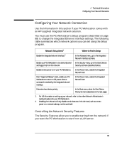
4 Technical Information System Connectors and Switches Switch 1 is reserved and should not be used. Its default position is Up. Switches 2 through 5 are used for processor settings as shown in the following table and should be changed if the processor supplied with the PC Workstation is replaced with a faster one. Switch 2 UP1 Switch 3 UP Switch 4 DOWN Switch 5 DOWN Bus Speed 100 MHz UP DOWN UP UP 100 MHz UP DOWN UP DOWN 100 MHz UP DOWN DOWN UP 100 MHz 1. UP=OFF, DOWN=ON. Processor Speed 350 MHz 400 MHz 450 MHz 500 MHz Switches 6 to 10 are used as shown in the following table: Switch1 Use Switch to: 1 - RESERVED 6 - CLEAR CMOS Do not use. Retain or clear CMOS memory: • UP to retain CMOS memory - DEFAULT • DOWN to clear CMOS memory. 7 - PSWRD Enable or clear (and disable) User and System Administrator Passwords stored in EEPROM: • UP to enable passwords - DEFAULT • DOWN to clear passwords. 8 - KEYB power on Enable or disable power on using the keyboard: • UP to disable keyboard power on • DOWN to enable keyboard power on - DEFAULT 86 English
-
 1
1 -
2
-
3
-
4
-
5
-
6
-
7
-
8
-
9
-
10
-
11
-
12
-
13
-
14
-
15
-
16
-
17
-
18
-
19
-
20
-
21
-
22
-
23
-
24
-
25
-
26
-
27
-
28
-
29
-
30
-
31
-
32
-
33
-
34
-
35
-
36
-
37
-
38
-
39
-
40
-
41
-
42
-
43
-
44
-
45
-
46
-
47
-
48
-
49
-
50
-
51
-
52
-
53
-
54
-
55
-
56
-
57
-
58
-
59
-
60
-
61
-
62
-
63
-
64
-
65
-
66
-
67
-
68
-
69
-
70
-
71
-
72
-
73
-
74
-
75
-
76
-
77
-
78
-
79
-
80
-
81
-
82
-
83
-
84
-
85
-
86
-
87
-
88
-
89
-
90
-
 91
91 -
 92
92 -
 93
93 -
 94
94 -
 95
95 -
 96
96 -
 97
97 -
 98
98 -
 99
99 -
 100
100 -
 101
101 -
102
-
103
-
104
 |
 |
