HP LaserJet Pro P1102 HP LaserJet Professional P1100 Series Printer - Service - Page 15
List of s
 |
View all HP LaserJet Pro P1102 manuals
Add to My Manuals
Save this manual to your list of manuals |
Page 15 highlights
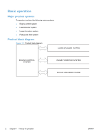
List of figures Figure 1-1 Product block diagram ...2 Figure 1-2 Engine-control system ...7 Figure 1-3 Motors ...8 Figure 1-4 Solenoids and clutches ...9 Figure 1-5 Switches ...9 Figure 1-6 Sensors ...10 Figure 1-7 DC controller block diagram ...11 Figure 1-8 Fuser control circuit ...12 Figure 1-9 Fuser-heater control circuit ...14 Figure 1-10 Low-voltage power supply (LVPS 16 Figure 1-11 High-voltage power supply ...18 Figure 1-12 Laser/scanner system ...19 Figure 1-13 Electrophotographic process block diagram (1 of 2 21 Figure 1-14 Electrophotographic process block diagram (2 of 2 22 Figure 1-15 Image formation process ...23 Figure 1-16 Primary charging ...24 Figure 1-17 Laser beam exposure ...24 Figure 1-18 Print cartridge ...25 Figure 1-19 Transfer ...26 Figure 1-20 Separation ...26 Figure 1-21 Fusing ...27 Figure 1-22 Drum cleaning ...27 Figure 1-23 Pickup, feed, and delivery system block diagram 28 Figure 1-24 Photo sensors, motor, and solenoid 29 Figure 2-1 Phillips and pozidrive screwdriver comparison 33 Figure 2-2 Parts removal order ...36 Figure 2-3 Remove the pickup roller (1 of 2) ...37 Figure 2-4 Remove the pickup roller (2 of 2) ...37 Figure 2-5 Remove the separation pad assembly 38 Figure 2-6 Remove the transfer roller ...39 Figure 2-7 Remove the tray ...40 Figure 2-8 Remove the output bin tray extension 41 Figure 2-9 Remove the front cover ...42 Figure 2-10 Remove the left cover (1 of 5) ...43 ENWW xiii
-
 1
1 -
2
-
3
-
4
-
5
-
6
-
7
-
8
-
9
-
 10
10 -
 11
11 -
 12
12 -
 13
13 -
 14
14 -
 15
15 -
 16
16 -
 17
17 -
 18
18 -
 19
19 -
 20
20 -
21
-
22
-
23
-
24
-
25
-
26
-
27
-
28
-
29
-
30
-
31
-
32
-
33
-
34
-
35
-
36
-
37
-
38
-
39
-
40
-
41
-
42
-
43
-
44
-
45
-
46
-
47
-
48
-
49
-
50
-
51
-
52
-
53
-
54
-
55
-
56
-
57
-
58
-
59
-
60
-
61
-
62
-
63
-
64
-
65
-
66
-
67
-
68
-
69
-
70
-
71
-
72
-
73
-
74
-
75
-
76
-
77
-
78
-
79
-
80
-
81
-
82
-
83
-
84
-
85
-
86
-
87
-
88
-
89
-
90
-
91
-
92
-
93
-
94
-
95
-
96
-
97
-
98
-
99
-
100
-
101
-
102
-
103
-
104
-
105
-
106
-
107
-
108
-
109
-
110
-
111
-
112
-
113
-
114
-
115
-
116
-
117
-
118
-
119
-
120
-
121
-
122
-
123
-
124
-
125
-
126
-
127
-
128
-
129
-
130
-
131
-
132
-
133
-
134
-
135
-
136
-
137
-
138
-
139
-
140
-
141
-
142
-
143
-
144
-
145
-
146
-
147
-
148
-
149
-
150
-
151
-
152
-
153
-
154
-
155
-
156
-
157
-
158
-
159
-
160
-
161
-
162
-
163
-
164
-
165
-
166
-
167
-
168
-
169
-
170
-
171
-
172
-
173
-
174
-
175
-
176
-
177
-
178
-
179
-
180
-
181
-
182
-
183
-
184
-
185
-
186
-
187
-
188
-
189
-
190
-
191
-
192
-
193
-
194
-
195
-
196
-
197
-
198
-
199
-
200
-
201
-
202
-
203
-
204
-
205
-
206
 |
 |