HP LaserJet Pro P1102 HP LaserJet Professional P1100 Series Printer - Service - Page 30
Fuser-control circuit,
 |
View all HP LaserJet Pro P1102 manuals
Add to My Manuals
Save this manual to your list of manuals |
Page 30 highlights
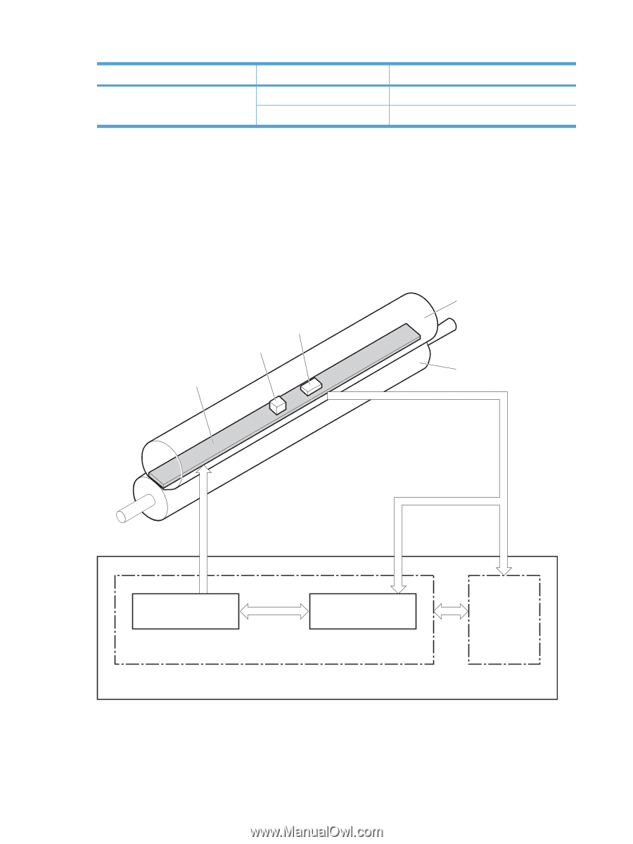
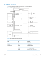
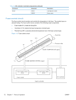
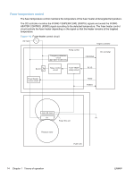
Table 1-6 DC controller controlled components (continued) Component Designator Switch SW501 SW502 Description Cartridge-door switch Power switch Fuser-control circuit The fuser-control circuit monitors and controls the temperature in the fuser. The product uses ondemand fusing. The fuser-control circuit consists of the following major components: ● Fuser heater (H1); heats the fusing film ● Thermistor (TH1); detects the fuser temperature (contact type) ● Thermal fuse (FU1); prevents abnormal temperature rise in the fuser (contact type) Figure 1-8 Fuser control circuit Fuser film TH1 FU1 H1 Pressure roller FUSER TEMPERATURE signal FUSER HEATER CONTROL signal Fuser heater control circuit Fuser control Fuser heater safety circuit Engine controller DC controller 12 Chapter 1 Theory of operation ENWW
-
 1
1 -
2
-
3
-
4
-
5
-
6
-
7
-
8
-
9
-
10
-
11
-
12
-
13
-
14
-
15
-
16
-
17
-
18
-
19
-
20
-
21
-
22
-
23
-
24
-
 25
25 -
 26
26 -
 27
27 -
 28
28 -
 29
29 -
 30
30 -
 31
31 -
 32
32 -
 33
33 -
 34
34 -
 35
35 -
36
-
37
-
38
-
39
-
40
-
41
-
42
-
43
-
44
-
45
-
46
-
47
-
48
-
49
-
50
-
51
-
52
-
53
-
54
-
55
-
56
-
57
-
58
-
59
-
60
-
61
-
62
-
63
-
64
-
65
-
66
-
67
-
68
-
69
-
70
-
71
-
72
-
73
-
74
-
75
-
76
-
77
-
78
-
79
-
80
-
81
-
82
-
83
-
84
-
85
-
86
-
87
-
88
-
89
-
90
-
91
-
92
-
93
-
94
-
95
-
96
-
97
-
98
-
99
-
100
-
101
-
102
-
103
-
104
-
105
-
106
-
107
-
108
-
109
-
110
-
111
-
112
-
113
-
114
-
115
-
116
-
117
-
118
-
119
-
120
-
121
-
122
-
123
-
124
-
125
-
126
-
127
-
128
-
129
-
130
-
131
-
132
-
133
-
134
-
135
-
136
-
137
-
138
-
139
-
140
-
141
-
142
-
143
-
144
-
145
-
146
-
147
-
148
-
149
-
150
-
151
-
152
-
153
-
154
-
155
-
156
-
157
-
158
-
159
-
160
-
161
-
162
-
163
-
164
-
165
-
166
-
167
-
168
-
169
-
170
-
171
-
172
-
173
-
174
-
175
-
176
-
177
-
178
-
179
-
180
-
181
-
182
-
183
-
184
-
185
-
186
-
187
-
188
-
189
-
190
-
191
-
192
-
193
-
194
-
195
-
196
-
197
-
198
-
199
-
200
-
201
-
202
-
203
-
204
-
205
-
206
 |
 |