HP LaserJet Pro P1102 HP LaserJet Professional P1100 Series Printer - Service - Page 29
DC controller operations,
 |
View all HP LaserJet Pro P1102 manuals
Add to My Manuals
Save this manual to your list of manuals |
Page 29 highlights
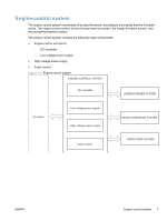
DC controller operations The DC controller controls the operational sequences of the product systems. Figure 1-7 DC controller block diagram Engine controller AC input Low-voltage power supply Motor Fuser unit Solenoid Transfer roller Cartridge High-voltage power supply DC controller Photointerrupter Switch Formatter Operation panel Table 1-6 DC controller controlled components Component Designator Motor M1 M2 Solenoid SL1 Photointerrupter PS701 PS702 PS751 PS901 ENWW Laser scanner Description Main motor Scanner motor Pickup solenoid Fuser delivery sensor Media width sensor Top-of-Page (TOP) sensor Main-motor rotation-number sensor Engine-control system 11
-
 1
1 -
2
-
3
-
4
-
5
-
6
-
7
-
8
-
9
-
10
-
11
-
12
-
13
-
14
-
15
-
16
-
17
-
18
-
19
-
20
-
21
-
22
-
23
-
 24
24 -
 25
25 -
 26
26 -
 27
27 -
 28
28 -
 29
29 -
 30
30 -
 31
31 -
 32
32 -
 33
33 -
 34
34 -
35
-
36
-
37
-
38
-
39
-
40
-
41
-
42
-
43
-
44
-
45
-
46
-
47
-
48
-
49
-
50
-
51
-
52
-
53
-
54
-
55
-
56
-
57
-
58
-
59
-
60
-
61
-
62
-
63
-
64
-
65
-
66
-
67
-
68
-
69
-
70
-
71
-
72
-
73
-
74
-
75
-
76
-
77
-
78
-
79
-
80
-
81
-
82
-
83
-
84
-
85
-
86
-
87
-
88
-
89
-
90
-
91
-
92
-
93
-
94
-
95
-
96
-
97
-
98
-
99
-
100
-
101
-
102
-
103
-
104
-
105
-
106
-
107
-
108
-
109
-
110
-
111
-
112
-
113
-
114
-
115
-
116
-
117
-
118
-
119
-
120
-
121
-
122
-
123
-
124
-
125
-
126
-
127
-
128
-
129
-
130
-
131
-
132
-
133
-
134
-
135
-
136
-
137
-
138
-
139
-
140
-
141
-
142
-
143
-
144
-
145
-
146
-
147
-
148
-
149
-
150
-
151
-
152
-
153
-
154
-
155
-
156
-
157
-
158
-
159
-
160
-
161
-
162
-
163
-
164
-
165
-
166
-
167
-
168
-
169
-
170
-
171
-
172
-
173
-
174
-
175
-
176
-
177
-
178
-
179
-
180
-
181
-
182
-
183
-
184
-
185
-
186
-
187
-
188
-
189
-
190
-
191
-
192
-
193
-
194
-
195
-
196
-
197
-
198
-
199
-
200
-
201
-
202
-
203
-
204
-
205
-
206
 |
 |
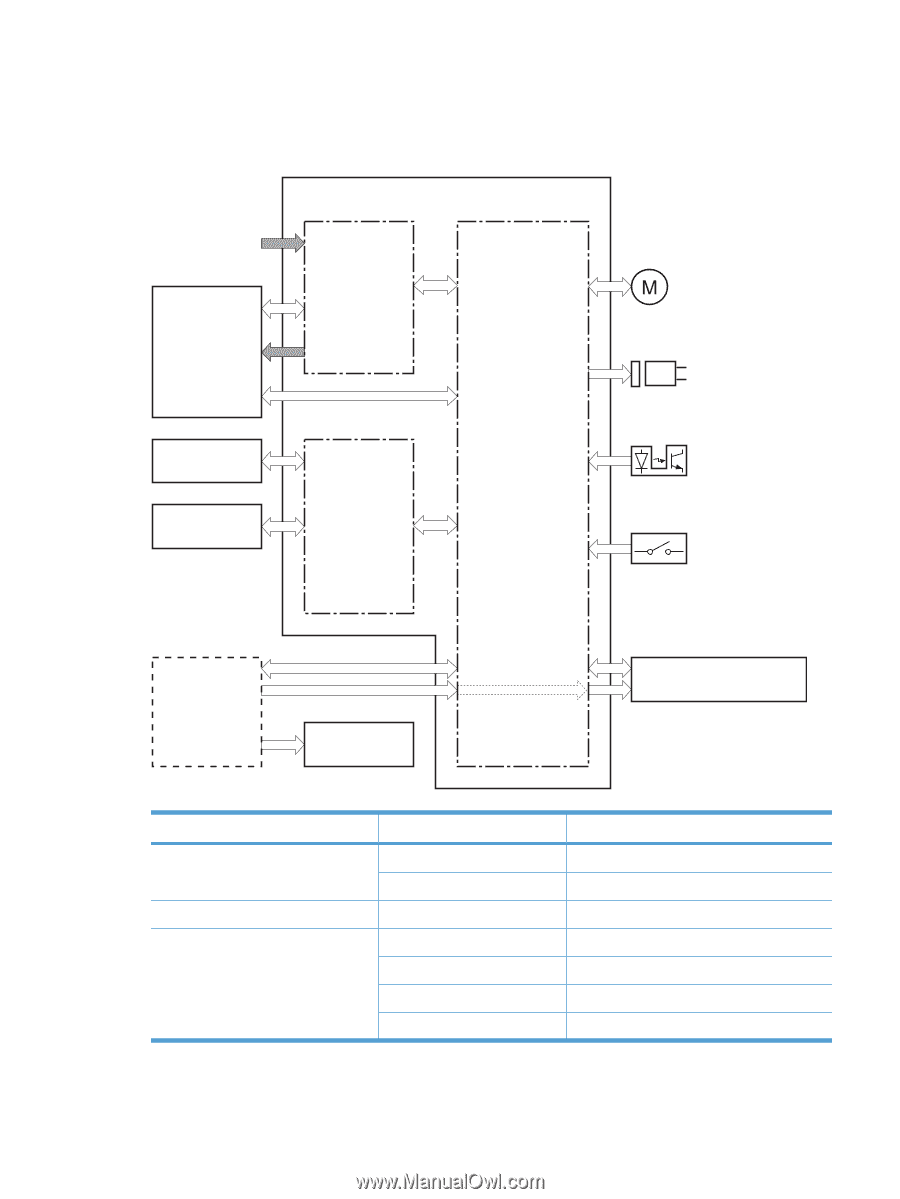
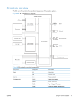
DC controller operations
The DC controller controls the operational sequences of the product systems.
Figure 1-7
DC controller block diagram
Transfer roller
Motor
Solenoid
Photointerrupter
Laser scanner
Formatter
Switch
Operation panel
Engine controller
Fuser unit
High-voltage
power supply
Cartridge
AC input
Low-voltage
power supply
DC controller
Table 1-6
DC controller controlled components
Component
Designator
Description
Motor
M1
Main motor
M2
Scanner motor
Solenoid
SL1
Pickup solenoid
Photointerrupter
PS701
Fuser delivery sensor
PS702
Media width sensor
PS751
Top-of-Page (TOP) sensor
PS901
Main-motor rotation-number sensor
ENWW
Engine-control system
11