HP ML370 ProLiant ML370 Generation 3 Server Maintenance and Service Guide - Page 72
Processor Cage Assembly, Remove the PPM. Refer to Processor Power Module in
 |
UPC - 613326765616
View all HP ML370 manuals
Add to My Manuals
Save this manual to your list of manuals |
Page 72 highlights
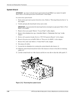
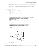
Removal and Replacement Procedures To replace the system board and all components connected to it, reverse steps 4 through 11. NOTE: Be sure that you align the six retaining guides on the chassis with the holes on the system board when replacing it. Processor Cage Assembly To remove the processor cage assembly: 1. Power down and remove power from the server. Refer to "Powering Down the Server" in this chapter. 2. Unlock the front bezel (tower server only). 3. Remove the access panel. Refer to "Access Panel" in this chapter. 4. Remove the processor air baffle. Refer to "Processor Air Baffle" in this chapter. 5. Remove the expansion boards. Refer to "PCI-X Expansion Boards" in this chapter. 6. Remove the center wall. Refer to "Center Wall" in this chapter. 7. Disconnect all cables. 8. Remove the system board. Refer to "System Board" in this chapter. 9. Remove the processor. Refer to "Processor Assembly" in this chapter. 10. Remove the PPM. Refer to "Processor Power Module" in this chapter. 11. Remove all DIMMs. Refer to "Removing DIMMs" in this chapter. 12. Remove the six processor cage screws using the Torx T-15 tool. NOTE: The Torx T-15 tool is clipped to the rear panel of the server to the right of the right-most fan grating. Figure 2-53: Removing the processor cage screws HP ProLiant ML370 Generation 3 Server Maintenance and Service Guide 2-57
-
 1
1 -
2
-
3
-
4
-
5
-
6
-
7
-
8
-
9
-
10
-
11
-
12
-
13
-
14
-
15
-
16
-
17
-
18
-
19
-
20
-
21
-
22
-
23
-
24
-
25
-
26
-
27
-
28
-
29
-
30
-
31
-
32
-
33
-
34
-
35
-
36
-
37
-
38
-
39
-
40
-
41
-
42
-
43
-
44
-
45
-
46
-
47
-
48
-
49
-
50
-
51
-
52
-
53
-
54
-
55
-
56
-
57
-
58
-
59
-
60
-
61
-
62
-
63
-
64
-
65
-
66
-
 67
67 -
 68
68 -
 69
69 -
 70
70 -
 71
71 -
 72
72 -
 73
73 -
 74
74 -
 75
75 -
 76
76 -
 77
77 -
78
-
79
-
80
-
81
-
82
-
83
-
84
-
85
-
86
-
87
-
88
-
89
-
90
-
91
-
92
-
93
-
94
-
95
-
96
-
97
-
98
-
99
-
100
-
101
-
102
-
103
-
104
-
105
-
106
-
107
-
108
-
109
-
110
-
111
-
112
-
113
 |
 |
