HP OMEN Transcend 14 Maintenance and Service GuideOMEN Transcend 14 inch Gamin - Page 56
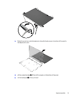
Separate the display from the computer while guiding the cables through the holes, in the top
 |
View all HP OMEN Transcend 14 manuals
Add to My Manuals
Save this manual to your list of manuals |
Page 56 highlights
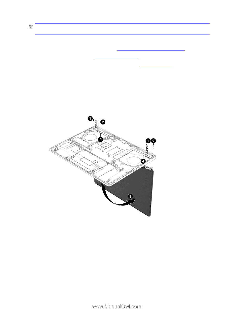
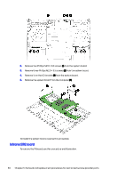
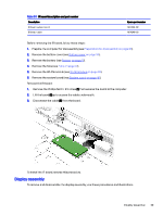
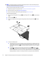
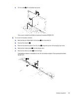
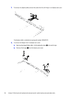
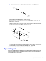
NOTE: The display assembly is spared at the subcomponent level. For display assembly spare part information, see the individual removal subsections. Before removing the display panel, follow these steps: 1. Prepare the computer for disassembly (see Preparation for disassembly on page 30). 2. Remove the bottom cover (see Bottom cover on page 30). 3. Disconnect the battery cable from the system board (see Battery on page 31). Remove the display assembly: 1. Remove the two Phillips M2.5 × 3.0 screws (1) and the Phillips M1.0 × 1.2 screw (2) from each display hinge. 2. Open the display (3) to 90°. 3. Separate the display from the computer while guiding the cables through the holes (4) in the top cover. 4. To remove the display panel: a. The display panel is secured to the display enclosure with tape that is installed under the left and right sides of the panel. The top of the panel is secured to the rear cover only with hooks. To remove the panel, use a tool (1) to pry the top of the panel away from the top of the display rear cover. b. Use tweezers to grasp the end of the tape on both sides of the panel (2). While turning the tweezers (3), wrap the tape around the tweezers as you continue to pull the tape out (4) from behind the display panel. You must pull the tape multiple times before it is completely removed. Display panel tape is available in the Adhesive Panel Kit as spare part number N84332-001. 50 Chapter 5 Removal and replacement procedures for authorized service provider parts
-
 1
1 -
2
-
3
-
4
-
5
-
6
-
7
-
8
-
9
-
10
-
11
-
12
-
13
-
14
-
15
-
16
-
17
-
18
-
19
-
20
-
21
-
22
-
23
-
24
-
25
-
26
-
27
-
28
-
29
-
30
-
31
-
32
-
33
-
34
-
35
-
36
-
37
-
38
-
39
-
40
-
41
-
42
-
43
-
44
-
45
-
46
-
47
-
48
-
49
-
50
-
 51
51 -
 52
52 -
 53
53 -
 54
54 -
 55
55 -
 56
56 -
 57
57 -
 58
58 -
 59
59 -
 60
60 -
 61
61 -
62
-
63
-
64
-
65
-
66
-
67
-
68
-
69
-
70
-
71
-
72
-
73
-
74
-
75
-
76
-
77
-
78
-
79
-
80
-
81
-
82
 |
 |