HP Presario 1600 Presario Select 1600 Series Maintenance and Service Guide - Page 57
Removing The Battery Charger Board
 |
View all HP Presario 1600 manuals
Add to My Manuals
Save this manual to your list of manuals |
Page 57 highlights
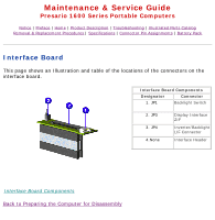
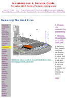
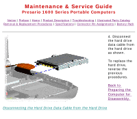
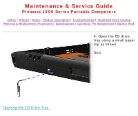
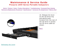
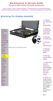
Maintenance & Service Guide Presario 1600 Series Portable Computers Notice | Preface | Home | Product Description | Troubleshooting | Illustrated Parts Catalog Removal & Replacement Procedures | Specifications | Connector Pin Assignments | Battery Pack Removing The Battery Charger Board Removing the Battery Pack Palmrest Cover with Touch Pad Keyboard Heatspreader Status Panel Interface Board Hard Drive Battery Charger Board CD Drive Removing the Screws and the Battery Charger Board Display Assembly Plastic Subpanel Assembly CD Drive Cable Speaker Assembly Modem Diskette Drive Fan Audio Assembly Board System Board Memory Module 1. Prepare the computer for disassembly. 2. Remove the palmrest cover with touch pad. 3. Remove the keyboard. 4. Remove the hard drives 5. Remove the stiffener bracket. 6. Remove the two screws from the battery charger board, unplug the board from the system board, and lift out of the chassis as shown. Back to Preparing the Computer for Disassembly NOTE: When replacing the battery charger board, ensure the pins are aligned with the connector on the system board.
-
 1
1 -
2
-
3
-
4
-
5
-
6
-
7
-
8
-
9
-
10
-
11
-
12
-
13
-
14
-
15
-
16
-
17
-
18
-
19
-
20
-
21
-
22
-
23
-
24
-
25
-
26
-
27
-
28
-
29
-
30
-
31
-
32
-
33
-
34
-
35
-
36
-
37
-
38
-
39
-
40
-
41
-
42
-
43
-
44
-
45
-
46
-
47
-
48
-
49
-
50
-
51
-
 52
52 -
 53
53 -
 54
54 -
 55
55 -
 56
56 -
 57
57 -
 58
58 -
 59
59 -
 60
60 -
 61
61 -
 62
62 -
63
-
64
-
65
-
66
-
67
-
68
-
69
-
70
-
71
-
72
-
73
-
74
-
75
-
76
-
77
-
78
-
79
-
80
-
81
-
82
-
83
-
84
-
85
-
86
-
87
-
88
 |
 |
