HP Server rp7420 HP 9000 rp7420 Server - User Service Guide, Fifth Edition - Page 52
Checking the Voltage, Verifying the Voltage Range of the Receptacle
 |
View all HP Server rp7420 manuals
Add to My Manuals
Save this manual to your list of manuals |
Page 52 highlights
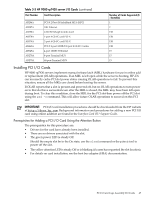
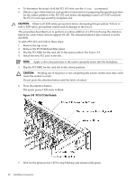
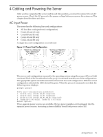
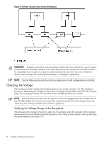
Figure 4-2 Power Source versus Power Distribution WARNING! Voltage is present at various locations within the server whenever a power source is connected. This voltage is present even when the main power switch is in the OFF position. To completely remove power, all power cords must be removed from the server. Failure to observe this warning can result in personal injury or damage to equipment. NOTE: System firmware prevents boot when a single power cord configuration is detected. Checking the Voltage This section provides voltage check information for use on the customer site. The emphasis focuses on measuring the voltages at the power cord plug end specified as an IEC 320 C19 type plug. This end plugs directly into the back of the HP 9000 rp7420 server chassis. NOTE: Perform these procedures for each power cord to be plugged directly into the back of the HP 9000 rp7420 server. If you do not get the expected results from this voltage check, see "Checking the Voltage (Additional Procedure)" (page 54). Verifying the Voltage Range of the Receptacle This measures the voltage between L1 and L2, L1 to ground, and L2 to ground. Three separate measurements are performed during this procedure. For voltage reference points when performing the measurements, see Figure 4-3. 52 Cabling and Powering the Server
-
 1
1 -
2
-
3
-
4
-
5
-
6
-
7
-
8
-
9
-
10
-
11
-
12
-
13
-
14
-
15
-
16
-
17
-
18
-
19
-
20
-
21
-
22
-
23
-
24
-
25
-
26
-
27
-
28
-
29
-
30
-
31
-
32
-
33
-
34
-
35
-
36
-
37
-
38
-
39
-
40
-
41
-
42
-
43
-
44
-
45
-
46
-
 47
47 -
 48
48 -
 49
49 -
 50
50 -
 51
51 -
 52
52 -
 53
53 -
 54
54 -
 55
55 -
 56
56 -
 57
57 -
58
-
59
-
60
-
61
-
62
-
63
-
64
-
65
-
66
-
67
-
68
-
69
-
70
-
71
-
72
-
73
-
74
-
75
-
76
-
77
-
78
-
79
-
80
-
81
-
82
-
83
-
84
-
85
-
86
-
87
-
88
-
89
-
90
-
91
-
92
-
93
-
94
-
95
-
96
-
97
-
98
-
99
-
100
-
101
-
102
-
103
-
104
-
105
-
106
-
107
-
108
-
109
-
110
-
111
-
112
-
113
-
114
-
115
-
116
-
117
-
118
-
119
-
120
-
121
-
122
-
123
-
124
-
125
-
126
-
127
 |
 |
