HP Server rp7420 HP 9000 rp7420 Server - User Service Guide, Fifth Edition - Page 55
MP Core I/O Connections, MP/SCSI Connections, Wall Receptacle Pinouts, WARNING
 |
View all HP Server rp7420 manuals
Add to My Manuals
Save this manual to your list of manuals |
Page 55 highlights
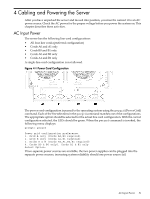
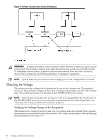
Figure 4-5 Wall Receptacle Pinouts WARNING! There is a risk of shock hazard while testing primary power. Use properly insulated probes. 5. Verify that the voltage between receptacle pins x and y is between 200 and 240 V AC. 6. Set the site power circuit breaker to Off. 7. Ensure that power is removed from the server. 8. Route and connect the server power connector to the site power receptacle. • For locking type receptacles, line up the key on the plug with the groove in the receptacle. • Push the plug into the receptacle and rotate to lock the connector in place. WARNING! Do not set site AC circuit breakers serving the processor cabinets to On before verifying that the cabinet has been wired into the site AC power supply correctly. Failure to do so might result in injury to personnel or damage to equipment when AC power is applied to the cabinet. 9. Set the site power circuit breaker to On. 10. Set the server power to On. 11. Check that the indicator light on each power supply is on. MP Core I/O Connections Each HP 9000 rp7420 server can have up to two MP core I/O board sets installed. Which allows two partitions to operate, or MP core I/O redundancy in a single partition configuration. Each MP core I/O board set consists of two boards: the MP/SCSI board and the LAN/SCSI board. The MP/SCSI board is oriented vertically and accessed from the back of the server. The LAN/SCSI is accessed from the PCI/PCI-X expansion card bay. Only the primary MP core I/O board set (MP/SCSI slot 1 and LAN/SCSI slot 8, chassis 1) is required for a single partition implementation. The secondary MP/SCSI board is not necessary for full operation. However, without the secondary MP/SCSI board, only two internal disks can be accessed. MP/SCSI Connections The MP/SCSI board is required to update firmware, access the console, turn partition power on or off, access all but two of the internal peripherals, and use other features of the server. Connections to the MP/SCSI board include the following: MP Core I/O Connections 55
-
 1
1 -
2
-
3
-
4
-
5
-
6
-
7
-
8
-
9
-
10
-
11
-
12
-
13
-
14
-
15
-
16
-
17
-
18
-
19
-
20
-
21
-
22
-
23
-
24
-
25
-
26
-
27
-
28
-
29
-
30
-
31
-
32
-
33
-
34
-
35
-
36
-
37
-
38
-
39
-
40
-
41
-
42
-
43
-
44
-
45
-
46
-
47
-
48
-
49
-
 50
50 -
 51
51 -
 52
52 -
 53
53 -
 54
54 -
 55
55 -
 56
56 -
 57
57 -
 58
58 -
 59
59 -
 60
60 -
61
-
62
-
63
-
64
-
65
-
66
-
67
-
68
-
69
-
70
-
71
-
72
-
73
-
74
-
75
-
76
-
77
-
78
-
79
-
80
-
81
-
82
-
83
-
84
-
85
-
86
-
87
-
88
-
89
-
90
-
91
-
92
-
93
-
94
-
95
-
96
-
97
-
98
-
99
-
100
-
101
-
102
-
103
-
104
-
105
-
106
-
107
-
108
-
109
-
110
-
111
-
112
-
113
-
114
-
115
-
116
-
117
-
118
-
119
-
120
-
121
-
122
-
123
-
124
-
125
-
126
-
127
 |
 |
