HP Server rp7420 HP 9000 rp7420 Server - User Service Guide, Fifth Edition - Page 56
LAN/SCSI Connections, Management Processor Access, Setting Up the Customer Engineer Tool (PC)
 |
View all HP Server rp7420 manuals
Add to My Manuals
Save this manual to your list of manuals |
Page 56 highlights
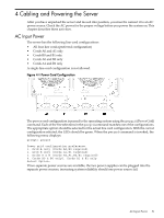
• DB25 connector, by way of the M cable This RS-232 connector provides connections for a local console, external modem, and a UPS. The server end of the M cable terminates in a DB25 connector. The opposite side of the cable terminates in three DB9 connectors labeled CONSOLE, UPS, and REMOTE. • 10/100 Base-T LAN RJ45 connector (for LAN and web console access). This LAN uses standby power and is still active if the front panel power switch is off and AC is present. • Internal LVD Ultra 160 SCSI channel for connections to internal mass storage • Internal SE Ultra SCSI channel for connection to an internal removable media device. LAN/SCSI Connections The LAN/SCSI board is a PCI form factor card that provides the basic external I/O connectivity for the system. Connections to the LAN/SCSI board include the following: • PCI-X to PCI-X bridge for multi-device compatibility. • Internal LVD Ultra 160 SCSI channel for connections to internal mass storage. • External LVD Ultra 160 SCSI channel connected to a 68-pin VHDCI connector. • 10/100/1000 Base-T LAN RJ45 connector. The primary LAN interface is located on the LAN/SCSI board installed in the right-most slot when viewing the system from the back. Management Processor Access NOTE: To access the MP for the initial installation, you must first connect the M cable to the DB25 connector located on the primary MP/SCSI board. The primary MP/SCSI board is located in the lower MP/SCSI board slot. Setting Up the Customer Engineer Tool (PC) The Customer Engineer (CE) Tool is usually a laptop. It enables communication with the MP in the HP 9000 rp7420 server. The MP monitors the activity of either a one partition or a multiple-partition configuration. During installation, communicating with the MP enables such tasks as: • Verifying that the components are present and installed correctly • Setting LAN IP addresses • Shutting off cell board power Communication with the MP is established by connecting the CE Tool to the local RS-232 port on the MP Core I/O card. Setting CE Tool Parameters After powering on the CE Tool, ensure the communications settings are as follows: • 8/none (parity) • 9600 baud • na (Receive) • na (Transmit) If the CE Tool is a laptop using Reflection, ensure communications settings are in place by following these steps: 1. From the Reflection Main screen, pull down the Connection menu and select Connection Setup. 56 Cabling and Powering the Server
-
 1
1 -
2
-
3
-
4
-
5
-
6
-
7
-
8
-
9
-
10
-
11
-
12
-
13
-
14
-
15
-
16
-
17
-
18
-
19
-
20
-
21
-
22
-
23
-
24
-
25
-
26
-
27
-
28
-
29
-
30
-
31
-
32
-
33
-
34
-
35
-
36
-
37
-
38
-
39
-
40
-
41
-
42
-
43
-
44
-
45
-
46
-
47
-
48
-
49
-
50
-
 51
51 -
 52
52 -
 53
53 -
 54
54 -
 55
55 -
 56
56 -
 57
57 -
 58
58 -
 59
59 -
 60
60 -
 61
61 -
62
-
63
-
64
-
65
-
66
-
67
-
68
-
69
-
70
-
71
-
72
-
73
-
74
-
75
-
76
-
77
-
78
-
79
-
80
-
81
-
82
-
83
-
84
-
85
-
86
-
87
-
88
-
89
-
90
-
91
-
92
-
93
-
94
-
95
-
96
-
97
-
98
-
99
-
100
-
101
-
102
-
103
-
104
-
105
-
106
-
107
-
108
-
109
-
110
-
111
-
112
-
113
-
114
-
115
-
116
-
117
-
118
-
119
-
120
-
121
-
122
-
123
-
124
-
125
-
126
-
127
 |
 |
