HP Visualize b1000 hp Visualize b1000, c3000, c3600 workstations parts replace - Page 42
Real Time Clock RTC Module
 |
View all HP Visualize b1000 manuals
Add to My Manuals
Save this manual to your list of manuals |
Page 42 highlights
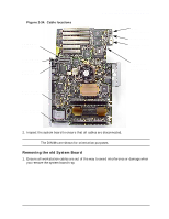
Parts Removal and Replacement Real Time Clock (RTC) Module Real Time Clock (RTC) Module This section describes how to remove and replace the Real Time Clock (RTC) Module. NOTE Prior to removing the Real Time Clock (RTC) Module, the Left Side Panel needs to be removed. See the appropriate section(s) for the steps to remove and replace this component. WARNING To avoid system damage, make sure your static-grounding strap is securely attached to your wrist and to bare metal on the workstation. Figure 2-36. RTC Module on the System Board Polarity Dot 6-pin power supply cable Removing the Real Time Clock (RTC) Module 1. Disconnect the 6-pin power supply cable from the system board and move the cable away from the system board. 2. Carefully remove the RTC Module from the system board. The RTC Module has a tight connection and may require a firm grip to remove it. Once removed, notice the polarity dots on the RTC Module and on the connector on the system board. 42 Chapter 2
-
 1
1 -
2
-
3
-
4
-
5
-
6
-
7
-
8
-
9
-
10
-
11
-
12
-
13
-
14
-
15
-
16
-
17
-
18
-
19
-
20
-
21
-
22
-
23
-
24
-
25
-
26
-
27
-
28
-
29
-
30
-
31
-
32
-
33
-
34
-
35
-
36
-
 37
37 -
 38
38 -
 39
39 -
 40
40 -
 41
41 -
 42
42 -
 43
43 -
 44
44 -
 45
45 -
 46
46 -
 47
47 -
48
 |
 |
