HP Z210 HP Z210 Workstation Series User Guide - Page 42
Preparing for component installation, Disassembly and installation preparation - sff workstation
 |
View all HP Z210 manuals
Add to My Manuals
Save this manual to your list of manuals |
Page 42 highlights
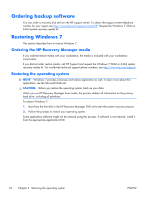
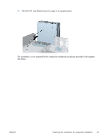
6 Preparing for component installation To facilitate the installation of components, several steps can be taken to prepare the workstation. This section describes how to prepare your workstation for component installation. Disassembly and installation preparation Use the following table to determine the order of workstation disassembly required before installing components. (Your workstation components may be different than those listed.) Table 6-1 Workstation component installation To install... Remove... Then remove... Then... Then... Memory Chassis locks* Side access panel Expansion card (PCI/ Chassis locks PCIe) Side access panel Hard drive Chassis locks Side access panel Rotate front drive cage to upward position (Z210 SFF) Rotate power supply to upright position (Z210 SFF) Optical drive Chassis locks Side access panel Remove front bezel * See the workstation Maintenance and Service Guide for chassis lock locations and operation instructions. Preparing the workstation for component installation To prepare the workstation: NOTE: The workstation contains green plastic touch points at locations where you must manipulate a button or lever. Green touch points on some components indicate tool-less removal of those components. 1. Disconnect power from the system. 2. Unlock the side access panel or remove any chassis locks. 3. Remove the side access panel as shown in the following illustrations. 34 Chapter 6 Preparing for component installation ENWW
-
 1
1 -
2
-
3
-
4
-
5
-
6
-
7
-
8
-
9
-
10
-
11
-
12
-
13
-
14
-
15
-
16
-
17
-
18
-
19
-
20
-
21
-
22
-
23
-
24
-
25
-
26
-
27
-
28
-
29
-
30
-
31
-
32
-
33
-
34
-
35
-
36
-
 37
37 -
 38
38 -
 39
39 -
 40
40 -
 41
41 -
 42
42 -
 43
43 -
 44
44 -
 45
45 -
 46
46 -
 47
47 -
48
-
49
-
50
-
51
-
52
-
53
-
54
-
55
-
56
-
57
-
58
-
59
-
60
-
61
-
62
-
63
-
64
-
65
-
66
-
67
-
68
 |
 |
