HP Z210 HP Z210 Workstation Series User Guide - Page 62
Caution,
 |
View all HP Z210 manuals
Add to My Manuals
Save this manual to your list of manuals |
Page 62 highlights
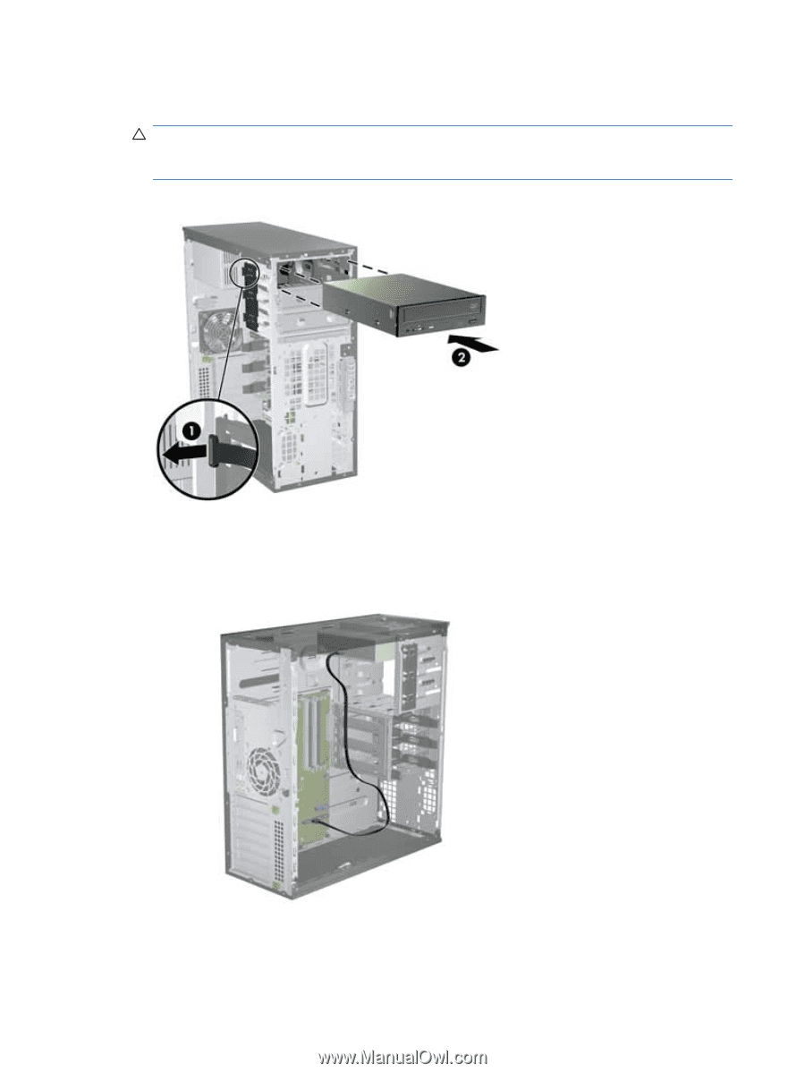
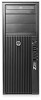
4. Align the screws with the grooves in the drive bay and gently slide the drive into the casing. Slide the drive completely in until it snaps into place. CAUTION: Verify that the optical disk drive is secure in the workstation chassis by pulling on the drive to see if it can be easily disengaged. Failure to properly secure the drive can damage the drive when moving the workstation. Figure 10-2 Inserting the ODD into the casing 5. Connect the power and data cables to the optical disk drive and system board as shown in the following figure. Refer to the side access panel service label for the location of the SATA connectors. Connect the data cable in the next available connector. Figure 10-3 Connecting ODD power and data cables 6. Replace all components that were removed in preparation for component installation. 54 Chapter 10 Installing optical disk drives ENWW
-
 1
1 -
2
-
3
-
4
-
5
-
6
-
7
-
8
-
9
-
10
-
11
-
12
-
13
-
14
-
15
-
16
-
17
-
18
-
19
-
20
-
21
-
22
-
23
-
24
-
25
-
26
-
27
-
28
-
29
-
30
-
31
-
32
-
33
-
34
-
35
-
36
-
37
-
38
-
39
-
40
-
41
-
42
-
43
-
44
-
45
-
46
-
47
-
48
-
49
-
50
-
51
-
52
-
53
-
54
-
55
-
56
-
 57
57 -
 58
58 -
 59
59 -
 60
60 -
 61
61 -
 62
62 -
 63
63 -
 64
64 -
 65
65 -
 66
66 -
 67
67 -
68
 |
 |