HP Z800 HP Z800 Workstation Maintenance and Service Guide - Page 98
Front bezel, Removing the front bezel
 |
UPC - 884962082454
View all HP Z800 manuals
Add to My Manuals
Save this manual to your list of manuals |
Page 98 highlights
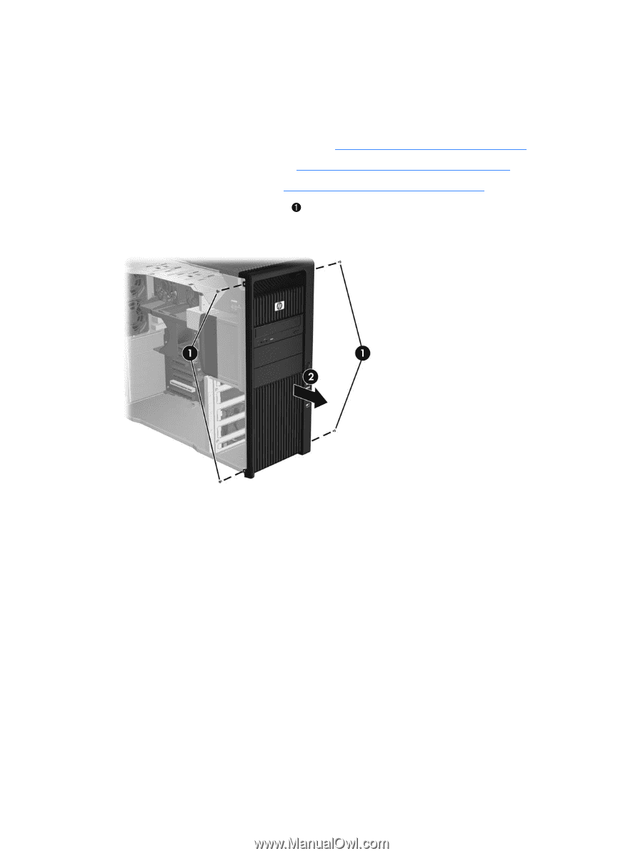
Front bezel This section describes how to remove and install the front bezel. Removing the front bezel 1. Disconnect power from the workstation (see Predisassembly procedures on page 74). 2. Remove the side access panel (see Removing the side access panel on page 76). 3. Remove the right side panel (see Removing the right side panel on page 81). 4. Remove the four T-15 Torx screws , and then remove the bezel from the chassis as shown in the following figure 2. Figure 5-15 Removing the front bezel Installing the front bezel To install the front bezel, position the bezel on the chassis and install the screws. 86 Chapter 5 Replacing components ENWW
-
 1
1 -
2
-
3
-
4
-
5
-
6
-
7
-
8
-
9
-
10
-
11
-
12
-
13
-
14
-
15
-
16
-
17
-
18
-
19
-
20
-
21
-
22
-
23
-
24
-
25
-
26
-
27
-
28
-
29
-
30
-
31
-
32
-
33
-
34
-
35
-
36
-
37
-
38
-
39
-
40
-
41
-
42
-
43
-
44
-
45
-
46
-
47
-
48
-
49
-
50
-
51
-
52
-
53
-
54
-
55
-
56
-
57
-
58
-
59
-
60
-
61
-
62
-
63
-
64
-
65
-
66
-
67
-
68
-
69
-
70
-
71
-
72
-
73
-
74
-
75
-
76
-
77
-
78
-
79
-
80
-
81
-
82
-
83
-
84
-
85
-
86
-
87
-
88
-
89
-
90
-
91
-
92
-
 93
93 -
 94
94 -
 95
95 -
 96
96 -
 97
97 -
 98
98 -
 99
99 -
 100
100 -
 101
101 -
 102
102 -
 103
103 -
104
-
105
-
106
-
107
-
108
-
109
-
110
-
111
-
112
-
113
-
114
-
115
-
116
-
117
-
118
-
119
-
120
-
121
-
122
-
123
-
124
-
125
-
126
-
127
-
128
-
129
-
130
-
131
-
132
-
133
-
134
-
135
-
136
-
137
-
138
-
139
-
140
-
141
-
142
-
143
-
144
-
145
-
146
-
147
-
148
-
149
-
150
-
151
-
152
-
153
-
154
-
155
-
156
-
157
-
158
-
159
-
160
-
161
-
162
-
163
-
164
-
165
-
166
-
167
-
168
-
169
-
170
-
171
-
172
-
173
-
174
-
175
-
176
-
177
-
178
-
179
-
180
-
181
-
182
-
183
-
184
-
185
-
186
-
187
-
188
-
189
-
190
-
191
-
192
-
193
-
194
-
195
-
196
-
197
-
198
-
199
-
200
-
201
-
202
-
203
-
204
-
205
-
206
-
207
-
208
-
209
-
210
-
211
-
212
-
213
-
214
-
215
-
216
-
217
-
218
-
219
-
220
-
221
-
222
-
223
-
224
-
225
-
226
-
227
-
228
-
229
-
230
-
231
-
232
-
233
-
234
-
235
-
236
-
237
-
238
-
239
-
240
-
241
-
242
-
243
-
244
-
245
-
246
-
247
-
248
-
249
-
250
-
251
-
252
-
253
-
254
-
255
-
256
-
257
-
258
-
259
-
260
-
261
-
262
-
263
-
264
-
265
-
266
 |
 |
Front bezel
This section describes how to remove and install the front bezel.
Removing the front bezel
1.
Disconnect power from the workstation (see
Predisassembly procedures
on page
74
).
2.
Remove the side access panel (see
Removing the side access panel
on page
76
).
3.
Remove the right side panel (see
Removing the right side panel
on page
81
).
4.
Remove the four T-15 Torx screws
, and then remove the bezel from the chassis as shown in
the following figure
2
.
Figure 5-15
Removing the front bezel
Installing the front bezel
To install the front bezel, position the bezel on the chassis and install the screws.
86
Chapter 5
Replacing components
ENWW