HP ZBook 17 Maintenance and Service Guide - Page 87
Heat sink for use with models with UMA graphics memory
 |
View all HP ZBook 17 manuals
Add to My Manuals
Save this manual to your list of manuals |
Page 87 highlights
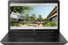
2. The following illustration shows the replacement thermal material locations. The thermal material must be thoroughly cleaned from the surfaces of the heat sink and the system board components each time the heat sink is removed. Replacement thermal material is included with the heat sink and system board spare part kits. Thermal paste is used on the system board components (2), (4), (6) and on the heat sink areas (1), (3), (5) that service them. Heat sink for use with models with UMA graphics memory 1. Remove the screws in the order shown (1 - 4) and then remove the heat sink (5) from the system board. Component replacement procedures 73
-
 1
1 -
2
-
3
-
4
-
5
-
6
-
7
-
8
-
9
-
10
-
11
-
12
-
13
-
14
-
15
-
16
-
17
-
18
-
19
-
20
-
21
-
22
-
23
-
24
-
25
-
26
-
27
-
28
-
29
-
30
-
31
-
32
-
33
-
34
-
35
-
36
-
37
-
38
-
39
-
40
-
41
-
42
-
43
-
44
-
45
-
46
-
47
-
48
-
49
-
50
-
51
-
52
-
53
-
54
-
55
-
56
-
57
-
58
-
59
-
60
-
61
-
62
-
63
-
64
-
65
-
66
-
67
-
68
-
69
-
70
-
71
-
72
-
73
-
74
-
75
-
76
-
77
-
78
-
79
-
80
-
81
-
 82
82 -
 83
83 -
 84
84 -
 85
85 -
 86
86 -
 87
87 -
 88
88 -
 89
89 -
 90
90 -
 91
91 -
 92
92 -
93
-
94
-
95
-
96
-
97
-
98
-
99
-
100
-
101
-
102
-
103
-
104
-
105
-
106
-
107
-
108
-
109
-
110
-
111
-
112
-
113
-
114
-
115
-
116
-
117
-
118
-
119
-
120
-
121
-
122
-
123
-
124
-
125
-
126
-
127
-
128
-
129
-
130
-
131
-
132
-
133
-
134
-
135
-
136
-
137
-
138
-
139
-
140
-
141
-
142
-
143
-
144
-
145
-
146
-
147
-
148
-
149
-
150
-
151
-
152
-
153
-
154
-
155
-
156
-
157
-
158
-
159
-
160
-
161
-
162
-
163
-
164
-
165
-
166
-
167
-
168
-
169
-
170
-
171
-
172
-
173
-
174
-
175
-
176
-
177
-
178
-
179
-
180
-
181
-
182
-
183
-
184
-
185
-
186
-
187
-
188
-
189
-
190
-
191
-
192
-
193
-
194
-
195
-
196
-
197
-
198
-
199
-
200
-
201
-
202
-
203
-
204
-
205
-
206
-
207
-
208
-
209
-
210
-
211
-
212
-
213
-
214
-
215
-
216
 |
 |

2.
The following illustration shows the replacement thermal material locations. The thermal material must
be thoroughly cleaned from the surfaces of the heat sink and the system board components each time
the heat sink is removed. Replacement thermal material is included with the heat sink and system board
spare part kits.
Thermal paste is used on the system board components
(2), (4), (6)
and on the heat sink areas
(1), (3),
(5)
that service them.
Heat sink for use with models with UMA graphics memory
1.
Remove the screws in the order shown
(1 – 4)
and then remove the heat sink
(5)
from the system board.
Component replacement procedures
73