HP c3700 hp Visualize b2000 UNIX workstation service handbook (a5983-90039) - Page 115
Replacing or Installing Additional Memory DIMMs - review
 |
View all HP c3700 manuals
Add to My Manuals
Save this manual to your list of manuals |
Page 115 highlights
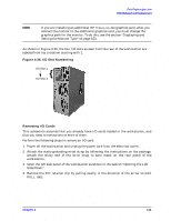
Field Replaceable Units FRU Removal and Replacement 2. Press downward on the ejector tabs located on both sides of the DIMM connector. See Figure 4-41. This raises the DIMM card for easy extraction. Figure 4-41. Removing Memory Cards Ejector Tab Ejector Tab 3. Lift up evenly on the outside edges of the DIMM card to remove it. See Figure 4-41. 4. Reinstall the remaining DIMM cards in the correct order by following the instructions in the next section, "Replacing or Installing Additional Memory DIMMs." Refer to Figure 4-43 or the B2000 system label located on the chassis floor for the proper loading sequence for the DIMM cards. 5. Close the left side panel of the workstation as explained in the section "Closing the Left Side Panel" and plug the workstation's power cord into the electrical outlet. 6. Verify that the reinstallation of the remaining DIMM cards was successful by following the steps in the section "Displaying the Current Memory Configuration" on page 156. Replacing or Installing Additional Memory DIMMs Before continuing with this section, carefully read the following list of considerations: • Use the procedure described in "Displaying the Current Memory Configuration" on page 156 before attempting to install additional memory DIMMs in the workstation. • Review the steps involved in installing DIMMs before you begin. • Insert DIMMs in the order shown in Figure 4-43 or in the B2000 system label located on the floor of the workstation chassis. • Note the proper orientation for DIMMs when inserting them into their connectors. • Use the Boot Console Handler to verify that the system recognizes the additional DIMMs when you have finished installation. WARNING Power off the workstation and unplug the power cord before replacing or installing additional memory DIMMs. Chapter 4 115
-
 1
1 -
2
-
3
-
4
-
5
-
6
-
7
-
8
-
9
-
10
-
11
-
12
-
13
-
14
-
15
-
16
-
17
-
18
-
19
-
20
-
21
-
22
-
23
-
24
-
25
-
26
-
27
-
28
-
29
-
30
-
31
-
32
-
33
-
34
-
35
-
36
-
37
-
38
-
39
-
40
-
41
-
42
-
43
-
44
-
45
-
46
-
47
-
48
-
49
-
50
-
51
-
52
-
53
-
54
-
55
-
56
-
57
-
58
-
59
-
60
-
61
-
62
-
63
-
64
-
65
-
66
-
67
-
68
-
69
-
70
-
71
-
72
-
73
-
74
-
75
-
76
-
77
-
78
-
79
-
80
-
81
-
82
-
83
-
84
-
85
-
86
-
87
-
88
-
89
-
90
-
91
-
92
-
93
-
94
-
95
-
96
-
97
-
98
-
99
-
100
-
101
-
102
-
103
-
104
-
105
-
106
-
107
-
108
-
109
-
 110
110 -
 111
111 -
 112
112 -
 113
113 -
 114
114 -
 115
115 -
 116
116 -
 117
117 -
 118
118 -
 119
119 -
 120
120 -
121
-
122
-
123
-
124
-
125
-
126
-
127
-
128
-
129
-
130
-
131
-
132
-
133
-
134
-
135
-
136
-
137
-
138
-
139
-
140
-
141
-
142
-
143
-
144
-
145
-
146
-
147
-
148
-
149
-
150
-
151
-
152
-
153
-
154
-
155
-
156
-
157
-
158
-
159
-
160
-
161
-
162
-
163
-
164
-
165
-
166
-
167
-
168
-
169
-
170
-
171
-
172
-
173
-
174
-
175
-
176
-
177
-
178
-
179
-
180
-
181
-
182
-
183
-
184
-
185
-
186
-
187
-
188
-
189
-
190
-
191
-
192
-
193
-
194
-
195
-
196
-
197
-
198
-
199
-
200
-
201
-
202
-
203
-
204
 |
 |
