HP c3700 hp Visualize b2000 UNIX workstation service handbook (a5983-90039) - Page 119
Power Supply
 |
View all HP c3700 manuals
Add to My Manuals
Save this manual to your list of manuals |
Page 119 highlights
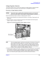
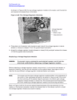
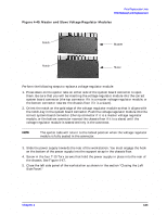
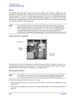
Field Replaceable Units FRU Removal and Replacement Power Supply This section explains how to remove and replace the power supply in the B2000 workstation. Removing the Power Supply WARNING To prevent injury, unplug the workstation's power cord from the electrical outlet before removing the power supply. Perform the following steps to remove the power supply: 1. Open the left side panel of the workstation as shown in the section "Opening the Left Side Panel." 2. Unplug the three power supply cables from the system board. 3. Remove the rear cover of the CD drive bay and disconnect the power cable. To do this, see the section "Removing and Replacing a CD Drive" on page 91. 4. Remove the rear cover of the floppy disk drive bay and disconnect the power cable, if the optional floppy disk drive is installed. To do this, see the section "Removing a Floppy Disk Drive" on page 96. 5. Detach the bundled power cables from the cable management clips on the chassis floor. See Figure 4-46. Figure 4-46. Screws Holding the Power Supply in Place Four T-15 Torx Screws Power Supply Cable Management Clips 6. Remove the four T-15 Torx screws from the rear of the chassis that hold the power supply in place, as shown in Figure 4-46. 7. Slide the power supply towards the front of the workstation. You must disengage the hook on the bottom of the power supply from the support strap in the chassis floor. Then remove the power supply from the workstation chassis. Chapter 4 119
-
 1
1 -
2
-
3
-
4
-
5
-
6
-
7
-
8
-
9
-
10
-
11
-
12
-
13
-
14
-
15
-
16
-
17
-
18
-
19
-
20
-
21
-
22
-
23
-
24
-
25
-
26
-
27
-
28
-
29
-
30
-
31
-
32
-
33
-
34
-
35
-
36
-
37
-
38
-
39
-
40
-
41
-
42
-
43
-
44
-
45
-
46
-
47
-
48
-
49
-
50
-
51
-
52
-
53
-
54
-
55
-
56
-
57
-
58
-
59
-
60
-
61
-
62
-
63
-
64
-
65
-
66
-
67
-
68
-
69
-
70
-
71
-
72
-
73
-
74
-
75
-
76
-
77
-
78
-
79
-
80
-
81
-
82
-
83
-
84
-
85
-
86
-
87
-
88
-
89
-
90
-
91
-
92
-
93
-
94
-
95
-
96
-
97
-
98
-
99
-
100
-
101
-
102
-
103
-
104
-
105
-
106
-
107
-
108
-
109
-
110
-
111
-
112
-
113
-
 114
114 -
 115
115 -
 116
116 -
 117
117 -
 118
118 -
 119
119 -
 120
120 -
 121
121 -
 122
122 -
 123
123 -
 124
124 -
125
-
126
-
127
-
128
-
129
-
130
-
131
-
132
-
133
-
134
-
135
-
136
-
137
-
138
-
139
-
140
-
141
-
142
-
143
-
144
-
145
-
146
-
147
-
148
-
149
-
150
-
151
-
152
-
153
-
154
-
155
-
156
-
157
-
158
-
159
-
160
-
161
-
162
-
163
-
164
-
165
-
166
-
167
-
168
-
169
-
170
-
171
-
172
-
173
-
174
-
175
-
176
-
177
-
178
-
179
-
180
-
181
-
182
-
183
-
184
-
185
-
186
-
187
-
188
-
189
-
190
-
191
-
192
-
193
-
194
-
195
-
196
-
197
-
198
-
199
-
200
-
201
-
202
-
203
-
204
 |
 |
