HP c3700 hp Visualize b2000 UNIX workstation service handbook (a5983-90039) - Page 83
Tools Required, Exploded View Diagram
 |
View all HP c3700 manuals
Add to My Manuals
Save this manual to your list of manuals |
Page 83 highlights
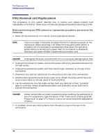
Field Replaceable Units Chapter Overview Tools Required Use the following tools to remove or replace FRUs in the B2000 workstation: • Torx T-15 driver • Light-duty flat blade screw driver with 6-inch (150 mm) blade • Needle-nose pliers • ESD equipment (see "Electrostatic Discharge (ESD) Precautions" on page 177) Exploded View Diagram Figure 4-1 shows an exploded view of the FRUs in the B2000 workstation. Refer to this figure for the locations of the various workstation FRUs while performing the FRU removal and replacement procedures in this chapter. Figure 4-1. Exploded View Diagram of the B2000 Workstation FRUs I/O Fan in Bracket Air Divider PCI Retainer Clip System Fan DIMM Cards Speaker Chassis CD Drive Bracket Battery Floppy Disk Drive Bracket Left Side Panel Power Supply Hard Disk Drive and Bracket Voltage Regulator Modules (Master and Slave) Front Panel System Board Tray Assembly Chapter 4 83
-
 1
1 -
2
-
3
-
4
-
5
-
6
-
7
-
8
-
9
-
10
-
11
-
12
-
13
-
14
-
15
-
16
-
17
-
18
-
19
-
20
-
21
-
22
-
23
-
24
-
25
-
26
-
27
-
28
-
29
-
30
-
31
-
32
-
33
-
34
-
35
-
36
-
37
-
38
-
39
-
40
-
41
-
42
-
43
-
44
-
45
-
46
-
47
-
48
-
49
-
50
-
51
-
52
-
53
-
54
-
55
-
56
-
57
-
58
-
59
-
60
-
61
-
62
-
63
-
64
-
65
-
66
-
67
-
68
-
69
-
70
-
71
-
72
-
73
-
74
-
75
-
76
-
77
-
 78
78 -
 79
79 -
 80
80 -
 81
81 -
 82
82 -
 83
83 -
 84
84 -
 85
85 -
 86
86 -
 87
87 -
 88
88 -
89
-
90
-
91
-
92
-
93
-
94
-
95
-
96
-
97
-
98
-
99
-
100
-
101
-
102
-
103
-
104
-
105
-
106
-
107
-
108
-
109
-
110
-
111
-
112
-
113
-
114
-
115
-
116
-
117
-
118
-
119
-
120
-
121
-
122
-
123
-
124
-
125
-
126
-
127
-
128
-
129
-
130
-
131
-
132
-
133
-
134
-
135
-
136
-
137
-
138
-
139
-
140
-
141
-
142
-
143
-
144
-
145
-
146
-
147
-
148
-
149
-
150
-
151
-
152
-
153
-
154
-
155
-
156
-
157
-
158
-
159
-
160
-
161
-
162
-
163
-
164
-
165
-
166
-
167
-
168
-
169
-
170
-
171
-
172
-
173
-
174
-
175
-
176
-
177
-
178
-
179
-
180
-
181
-
182
-
183
-
184
-
185
-
186
-
187
-
188
-
189
-
190
-
191
-
192
-
193
-
194
-
195
-
196
-
197
-
198
-
199
-
200
-
201
-
202
-
203
-
204
 |
 |
