HP dx2310 Service Reference Guide: HP Compaq dx2310 MT/dx2318 MT Business PCs, - Page 44
Expansion Cards, 5.1 Expansion Slot Cover Lock
 |
View all HP dx2310 manuals
Add to My Manuals
Save this manual to your list of manuals |
Page 44 highlights
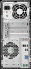
Removal and Replacement Procedures- Microtower (MT) Chassis ✎ A memory module can be installed in only one way. Match the notch on the module with the tab on the memory socket. 5. Push the module down into the socket, ensuring that the module is fully inserted and properly seated. Make sure the latches are in the closed position 3. 6. Repeat steps 4 and 5 for any additional modules that you want to install. To reassemble the computer, reverse the removal procedure. 6.5 Expansion Cards 6.5.1 Expansion Slot Cover Lock 1. Prepare the computer for disassembly (Section 6.1, "Preparation for Disassembly"). 2. Remove the right access panel (Section 6.2, "Remove the computer access panel and front bezel (MT chassis)"). 3. Lay the computer down on its side to make it easier to work on. 4. On the rear of the computer, remove the retaining screw 1 then, slide the slot cover lock up 2 to access the expansion slot cover. To reinstall the slot cover lock, reverse the removal procedure. 6-6 490778-001 Service Reference Guide
-
 1
1 -
2
-
3
-
4
-
5
-
6
-
7
-
8
-
9
-
10
-
11
-
12
-
13
-
14
-
15
-
16
-
17
-
18
-
19
-
20
-
21
-
22
-
23
-
24
-
25
-
26
-
27
-
28
-
29
-
30
-
31
-
32
-
33
-
34
-
35
-
36
-
37
-
38
-
 39
39 -
 40
40 -
 41
41 -
 42
42 -
 43
43 -
 44
44 -
 45
45 -
 46
46 -
 47
47 -
 48
48 -
 49
49 -
50
-
51
-
52
-
53
-
54
-
55
-
56
-
57
-
58
-
59
-
60
-
61
-
62
-
63
-
64
-
65
-
66
-
67
-
68
-
69
-
70
-
71
-
72
-
73
-
74
-
75
-
76
-
77
-
78
-
79
-
80
-
81
-
82
-
83
-
84
-
85
-
86
-
87
-
88
-
89
-
90
-
91
-
92
-
93
-
94
-
95
-
96
-
97
 |
 |
