HP dx2310 Service Reference Guide: HP Compaq dx2310 MT/dx2318 MT Business PCs, - Page 51
Removing a Drive, Drive Positions
 |
View all HP dx2310 manuals
Add to My Manuals
Save this manual to your list of manuals |
Page 51 highlights
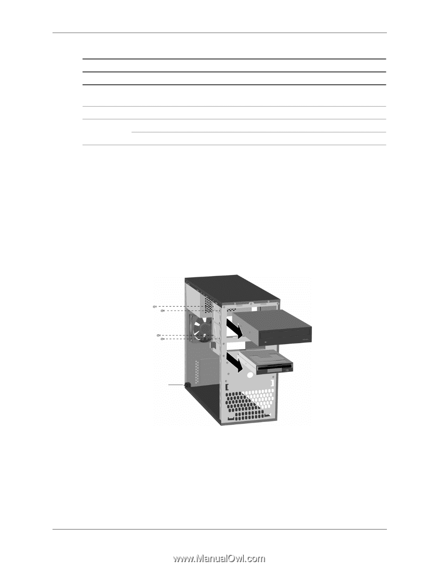
Removal and Replacement Procedures- Microtower (MT) Chassis Item 1 2 3 Drive Positions Description First 5.25-inch, half-height bays for optional drives Second 5.25-inch, half-height bays for optional drives One standard 3.5-inch, one-third height bays (1.44-MB diskette drive shown) One internal 3.5-inch, one-third height bays for hard drives An internal 3.5-inch bracket kit for second hard drives is available as option. 6.7.2 Removing a Drive 1. Turn off the computer properly through the operating system and turn off any external devices. Disconnect the power cord from the power outlet and disconnect any external devices. 2. Remove the access panel and front bezel. 3. Disconnect the power and data cables from the back of the drive, as indicated in the following illustrations. 4. Remove all the screws that secures the drives in the drive bay. Slide the drive disk forward and out of the bay. * * These apply for selected models and countries only. Removing the Drives Service Reference Guide 490778-001 6-13
-
 1
1 -
2
-
3
-
4
-
5
-
6
-
7
-
8
-
9
-
10
-
11
-
12
-
13
-
14
-
15
-
16
-
17
-
18
-
19
-
20
-
21
-
22
-
23
-
24
-
25
-
26
-
27
-
28
-
29
-
30
-
31
-
32
-
33
-
34
-
35
-
36
-
37
-
38
-
39
-
40
-
41
-
42
-
43
-
44
-
45
-
 46
46 -
 47
47 -
 48
48 -
 49
49 -
 50
50 -
 51
51 -
 52
52 -
 53
53 -
 54
54 -
 55
55 -
 56
56 -
57
-
58
-
59
-
60
-
61
-
62
-
63
-
64
-
65
-
66
-
67
-
68
-
69
-
70
-
71
-
72
-
73
-
74
-
75
-
76
-
77
-
78
-
79
-
80
-
81
-
82
-
83
-
84
-
85
-
86
-
87
-
88
-
89
-
90
-
91
-
92
-
93
-
94
-
95
-
96
-
97
 |
 |